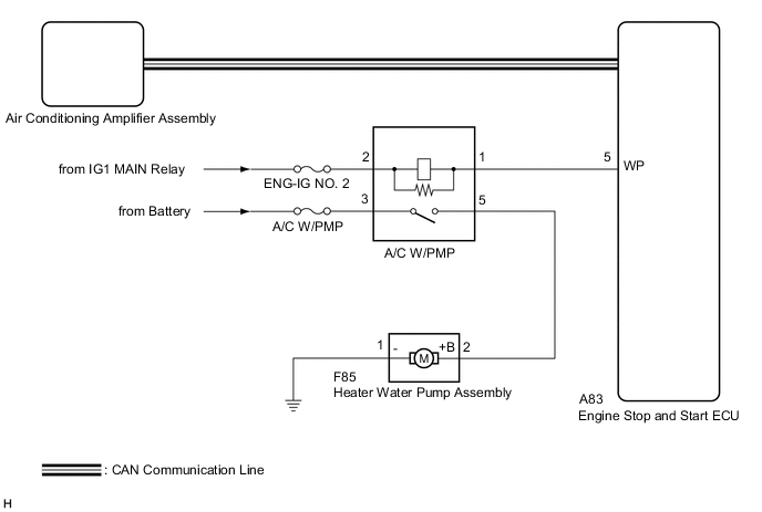
AIR CONDITIONING SYSTEM Heater Water Pump Circuit
DESCRIPTION
The heater water pump assembly supplies engine coolant to the heater radiator unit sub-assembly to prevent a decrease in the effectiveness of the heater when the engine is stopped by the stop and start system. According to signals from the air conditioning amplifier assembly, the engine stop and start ECU operates the heater water pump relay to operate the heater water pump assembly.
WIRING DIAGRAM
CAUTION / NOTICE / HINT
Note
Inspect the fuses for circuits related to this system before performing the following procedure.
PROCEDURE
-
PERFORM ACTIVE TEST USING GTS
-
Connect the GTS to the DLC3.
-
Turn the engine switch on (IG).
-
Turn the GTS on.
-
Enter the following menus: Powertrain / Stop and Start / Active Test.
-
Perform the Active Test according to the display on the GTS.
Powertrain > Stop and Start > Active TestTester Display Measurement Item Control Range Diagnostic Note Heater Core Water Pump Operates the heater water pump assembly ON / OFF
-
Engine switch on (IG)
-
Engine not running
Preconditions:
Note
This test activates heater water pump assembly only 10 seconds.
Powertrain > Stop and Start > Active TestTester Display Heater Core Water Pump OK The heater water pump assembly operates smoothly. Result Proceed to OK NG -
NG 
PROCEED TO NEXT SUSPECTED AREA SHOWN IN PROBLEM SYMPTOMS TABLE Click here
OK 
-
-
INSPECT HEATER WATER PUMP RELAY
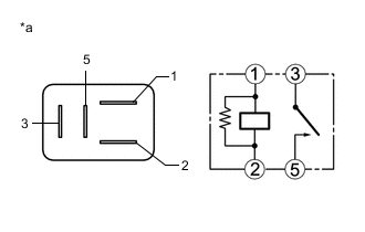
*a Component without harness connected
(Heater Water Pump Relay)
-
Remove the heater water pump relay from the No. 1 engine room relay block.
-
Measure the resistance according to the value(s) in the table below.
Standard Resistance Tester Connection Condition Specified Condition 3 - 5 Battery voltage not applied between terminals 1 and 2 10 kΩ or higher 3 - 5 Battery voltage applied between terminals 1 and 2 Below 1 Ω Result Proceed to OK NG
NG
REPLACE HEATER WATER PUMP RELAY Click here
OK
-
-
INSPECT HEATER WATER PUMP ASSEMBLY
-
Remove the heater water pump assembly.
-
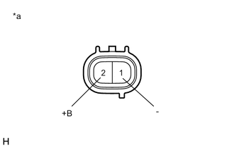
*a Component without harness connected
(Heater Water Pump Assembly)
Connect a positive (+) lead from the battery to terminal 2 (+B) and a negative (-) lead to terminal 1 (-).
OK The heater water pump assembly operates smoothly. Note
Perform this test within 10 seconds to prevent the coil from burning out.
Result Proceed to OK NG
NG
REPLACE HEATER WATER PUMP ASSEMBLY Click here
OK
-
-
CHECK HARNESS AND CONNECTOR (HEATER WATER PUMP RELAY - POWER SOURCE)
-
Measure the voltage according to the value(s) in the table below.
Standard Voltage Tester Connection Condition Specified Condition Relay terminal 2 - Body ground Engine switch on (IG) 11 to 14 V Relay terminal 2 - Body ground Engine switch off Below 1 V Relay terminal 3 - Body ground Always 11 to 14 V Result Proceed to OK NG
NG
REPAIR OR REPLACE HARNESS OR CONNECTOR
OK
-
-
CHECK HARNESS AND CONNECTOR (HEATER WATER PUMP ASSEMBLY - HEATER WATER PUMP RELAY, BODY GROUND)
-
Measure the resistance according to the value(s) in the table below.
Standard Resistance Tester Connection Condition Specified Condition F85-1 (-) - Body ground Always Below 1 Ω F85-2 (+B) - Relay terminal 5 Always Below 1 Ω F85-2 (+B) or Relay terminal 5 - Body ground Always 10 kΩ or higher Result Proceed to OK NG
NG
REPAIR OR REPLACE HARNESS OR CONNECTOR
OK
-
-
CHECK HARNESS AND CONNECTOR (HEATER WATER PUMP RELAY - ENGINE STOP AND START ECU)
-
Disconnect the A83 engine stop and start ECU connector.
-
Measure the resistance according to the value(s) in the table below.
Standard Resistance Tester Connection Condition Specified Condition Relay terminal 1 - A83-5 (WP) Always Below 1 Ω Relay terminal 1 or A83-5 (WP) - Body ground Always 10 kΩ or higher Result Proceed to OK NG
NG
REPAIR OR REPLACE HARNESS OR CONNECTOR
OK
-
-
INSPECT ENGINE STOP AND START ECU
-
Reconnect the A83 engine stop and start ECU connector.
-
Remove the engine stop and start ECU with the connectors still connected.
-
Measure the voltage according to the value(s) in the table below.
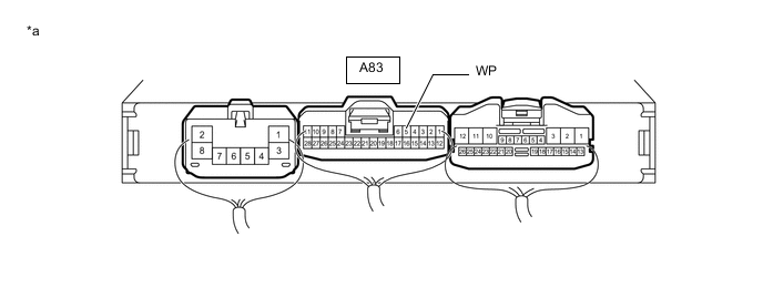
*a Component with harness connected
(Engine Stop and Start ECU)
- - Standard Voltage Tester Connection Condition Specified Condition A83-5 (WP) - Body ground
-
Engine stopped by stop and start system
-
A/C switch: on
Below 2 V
-
Engine not stopped by stop and start system
-
A/C switch: on
11 to 14 V Result Proceed to OK NG -
OK
REPLACE AIR CONDITIONING AMPLIFIER ASSEMBLY Click here
NG
REPLACE ENGINE STOP AND START ECU Click here
-