FRONT POWER SEAT CONTROL SYSTEM, Diagnostic DTC:B2653
| DTC Code | DTC Name |
|---|---|
| B2653 | Lifter Sensor Malfunction |
DESCRIPTION
When the position control ECU and switch assembly (driver seat) or position control ECU and switch assembly (front passenger seat) does not receive a sensor signal despite upward or downward movement of the seat cushion by power seat motor operation, this DTC is stored.
| DTC No. | Detection Item | DTC Detection Condition | Trouble Area |
|---|---|---|---|
| B2653 | Lifter Sensor Malfunction | The upward and downward lock detection position of the sensor is the same. |
|
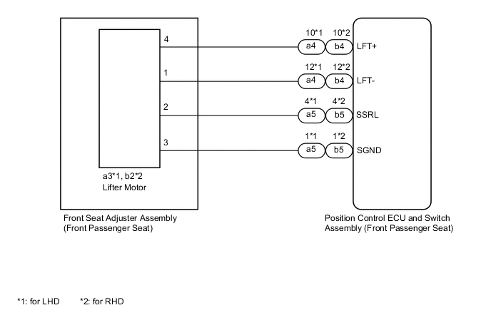
WIRING DIAGRAM
-
for Driver Seat
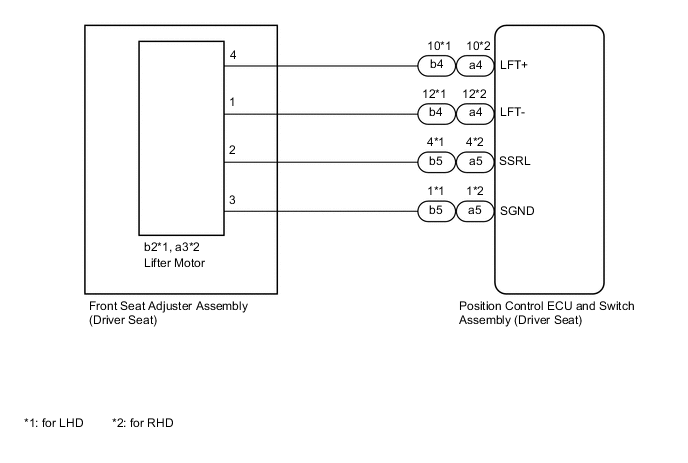
-
for Front Passenger Seat
PROCEDURE
-
CLEAR DTC
-
Clear the DTCs.
Body Electrical > Driver Seat > Clear DTCs
Body Electrical > Passenger Seat > Clear DTCsResult Proceed to NEXT
NEXT 
-
-
CHECK FOR DTC
-
Check for DTCs.
Body Electrical > Driver Seat > Trouble Codes
Body Electrical > Passenger Seat > Trouble CodesOK DTC B2653 is not output. Result Result Proceed to DTC B2653 is not output A DTC B2653 output from "Driver Seat" B DTC B2653 output from "Front Passenger Seat" C
A 
USE SIMULATION METHOD TO CHECK Click here
C 
PERFORM ACTIVE TEST USING GTS (LIFTER MOTOR) Click here
B
-
-
PERFORM ACTIVE TEST USING GTS (LIFTER MOTOR)
-
Connect the GTS to the DLC3.
-
Turn the engine switch on (IG).
-
Turn the GTS on.
-
Enter the following menus: Body Electrical / Driver Seat / Active Test.
-
Perform the Active Test according to the display on the GTS.
Body Electrical > Driver Seat > Active TestTester Display Measurement Item Control Range Diagnostic Note Lifter Operation Seat lifter operation OFF/Rear/Front -
Body Electrical > Driver Seat > Active TestTester Display Lifter Operation OK Motor operates normally. Result Proceed to OK NG
NG
INSPECT LIFTER MOTOR (FRONT SEAT ADJUSTER ASSEMBLY (DRIVER SEAT)) Click here
OK
-
-
CHECK POSITION CONTROL ECU AND SWITCH ASSEMBLY (DRIVER SEAT) (LIFTER MOTOR CIRCUIT)
-
Disconnect the b2*1 or a3*2 lifter motor (front seat adjuster assembly (driver seat)) connector.
-
*1: for LHD
-
*2: for RHD
-
-
Measure the voltage according to the value(s) in the table below.
Standard Voltage for LHD Tester Connection Condition Specified Condition b2-2 - b2-3 Lifter switch on 4.8 to 5.1 V for RHD Tester Connection Condition Specified Condition a3-2 - a3-3 Lifter switch on 4.8 to 5.1 V Result Proceed to OK NG
NG
CHECK HARNESS AND CONNECTOR (POSITION CONTROL ECU AND SWITCH ASSEMBLY (DRIVER SEAT) - LIFTER MOTOR (FRONT SEAT ADJUSTER ASSEMBLY (DRIVER SEAT))) Click here
OK
-
-
CHECK LIFTER MOTOR (FRONT SEAT ADJUSTER ASSEMBLY (DRIVER SEAT))
-
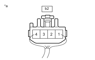
*A for LHD *B for RHD *a Component with harness connected
(Lifter Motor (Front Seat Adjuster Assembly (Driver Seat))
Reconnect the b2*1 or a3*2 lifter motor (front seat adjuster assembly (driver seat)) connector.
-
*1: for LHD
-
*2: for RHD
-
-
Measure the voltage according to the value(s) in the table below.
Standard Voltage for LHD Tester Connection Condition Specified Condition b2-2 - Body ground Lifter motor operating 4.5 to 4.8 V for RHD Tester Connection Condition Specified Condition a3-2 - Body ground Lifter motor operating 4.5 to 4.8 V Result Proceed to OK NG
OK
REPLACE POSITION CONTROL ECU AND SWITCH ASSEMBLY (DRIVER SEAT) Click here
NG
REPLACE SLIDE MOTOR (FRONT SEAT ADJUSTER ASSEMBLY (DRIVER SEAT)) Click here
-
-
CHECK HARNESS AND CONNECTOR (POSITION CONTROL ECU AND SWITCH ASSEMBLY (DRIVER SEAT) - LIFTER MOTOR (FRONT SEAT ADJUSTER ASSEMBLY (DRIVER SEAT)))
-
Disconnect the b5*1 or a5*2 position control ECU and switch assembly (driver seat) connector.
-
*1: for LHD
-
*2: for RHD
-
-
Measure the resistance according to the value(s) in the table below.
Standard Resistance for LHD Tester Connection Condition Specified Condition b5-4 (SSRL) - b2-2 Always Below 1 Ω b5-4 (SSRL) or b2-2 - Body ground Always 10 kΩ or higher b5-1 (SGND) - b2-3 Always Below 1 Ω b5-1 (SGND) or b2-3 - Body ground Always 10 kΩ or higher for RHD Tester Connection Condition Specified Condition a5-4 (SSRL) - a3-2 Always Below 1 Ω a5-4 (SSRL) or a3-2 - Body ground Always 10 kΩ or higher a5-1 (SGND) - a3-3 Always Below 1 Ω a5-1 (SGND) or a3-3 - Body ground Always 10 kΩ or higher Result Proceed to OK NG
OK
REPLACE POSITION CONTROL ECU AND SWITCH ASSEMBLY (DRIVER SEAT) Click here
NG
REPAIR OR REPLACE HARNESS OR CONNECTOR
-
-
INSPECT LIFTER MOTOR (FRONT SEAT ADJUSTER ASSEMBLY (DRIVER SEAT))
-
Remove the front seat adjuster assembly (driver seat).
-
Inspect the front seat adjuster assembly (driver seat) (lifter motor).
Result Proceed to OK NG
NG
REPLACE LIFTER MOTOR (FRONT SEAT ADJUSTER ASSEMBLY (DRIVER SEAT)) Click here
OK
-
-
CHECK HARNESS AND CONNECTOR (POSITION CONTROL ECU AND SWITCH ASSEMBLY (DRIVER SEAT) - LIFTER MOTOR (FRONT SEAT ADJUSTER ASSEMBLY (DRIVER SEAT)))
-
Disconnect the b4*1 or a4*2 position control ECU and switch assembly (driver seat) connector.
-
*1: for LHD
-
*2: for RHD
-
-
Measure the resistance according to the value(s) in the table below.
Standard Resistance for LHD Tester Connection Condition Specified Condition b4-10 (LFT+) - b2-4 Always Below 1 Ω b4-10 (LFT+) or b2-4 - Body ground Always 10 kΩ or higher b4-12 (LFT-) - b2-1 Always Below 1 Ω b4-12 (LFT-) or b2-1 - Body ground Always 10 kΩ or higher for RHD Tester Connection Condition Specified Condition a4-10 (LFT+) - a3-4 Always Below 1 Ω a4-10 (LFT+) or a3-4 - Body ground Always 10 kΩ or higher a4-12 (LFT-) - a3-1 Always Below 1 Ω a4-12 (LFT-) or a3-1 - Body ground Always 10 kΩ or higher Result Proceed to OK NG
OK
REPLACE POSITION CONTROL ECU AND SWITCH ASSEMBLY (DRIVER SEAT) Click here
NG
REPAIR OR REPLACE HARNESS OR CONNECTOR
-
-
PERFORM ACTIVE TEST USING GTS (LIFTER MOTOR)
-
Connect the GTS to the DLC3.
-
Turn the engine switch on (IG).
-
Turn the GTS on.
-
Enter the following menus: Body Electrical / Passenger Seat / Active Test.
-
Perform the Active Test according to the display on the GTS.
Body Electrical > Passenger Seat > Active TestTester Display Measurement Item Control Range Diagnostic Note Lifter Operation Seat lifter operation OFF/Rear/Front -
Body Electrical > Passenger Seat > Active TestTester Display Lifter Operation OK Motor operates normally. Result Proceed to OK NG
NG
INSPECT LIFTER MOTOR (FRONT SEAT ADJUSTER ASSEMBLY (FRONT PASSENGER SEAT)) Click here
OK
-
-
CHECK POSITION CONTROL ECU AND SWITCH ASSEMBLY (FRONT PASSENGER SEAT) (SLIDE MOTOR CIRCUIT)
-
Disconnect the a3*1 or b2*2 lifter motor (front seat adjuster assembly (front passenger seat)) connector.
-
*1: for LHD
-
*2: for RHD
-
-
Measure the voltage according to the value(s) in the table below.
Standard Voltage for LHD Tester Connection Condition Specified Condition a3-2 - a3-3 Lifter switch on 4.8 to 5.1 V for RHD Tester Connection Condition Specified Condition b2-2 - b2-3 Lifter switch on 4.8 to 5.1 V Result Proceed to OK NG
NG
CHECK HARNESS AND CONNECTOR (POSITION CONTROL ECU AND SWITCH ASSEMBLY (FRONT PASSENGER SEAT) - LIFTER MOTOR (FRONT SEAT ADJUSTER ASSEMBLY (FRONT PASS) Click here
OK
-
-
CHECK LIFTER MOTOR (FRONT SEAT ADJUSTER ASSEMBLY (FRONT PASSENGER SEAT))
-
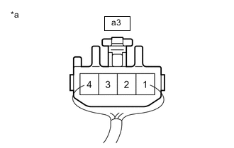
*A for LHD *B for RHD *a Component with harness connected
(Lifter Motor (Front Seat Adjuster Assembly (Front Passenger Seat))
Reconnect the a3*1 or b2*2 lifter motor (front seat adjuster assembly (front passenger seat)) connector.
-
*1: for LHD
-
*2: for RHD
-
-
Measure the voltage according to the value(s) in the table below.
Standard Voltage for LHD Tester Connection Condition Specified Condition a3-2 - Body ground Lifter motor operating 4.5 to 4.8 V for RHD Tester Connection Condition Specified Condition b2-2 - Body ground Lifter motor operating 4.5 to 4.8 V Result Proceed to OK NG
OK
REPLACE POSITION CONTROL ECU AND SWITCH ASSEMBLY (FRONT PASSENGER SEAT) Click here
NG
REPLACE LIFTER MOTOR (FRONT SEAT ADJUSTER ASSEMBLY (FRONT PASSENGER SEAT)) Click here
-
-
CHECK HARNESS AND CONNECTOR (POSITION CONTROL ECU AND SWITCH ASSEMBLY (FRONT PASSENGER SEAT) - LIFTER MOTOR (FRONT SEAT ADJUSTER ASSEMBLY (FRONT PASS)
-
Disconnect the a5*1 or b5*2 position control ECU and switch assembly (front passenger seat) connector.
-
*1: for LHD
-
*2: for RHD
-
-
Measure the resistance according to the value(s) in the table below.
Standard Resistance for LHD Tester Connection Condition Specified Condition a5-4 (SSRL) - a3-2 Always Below 1 Ω a5-4 (SSRL) or a3-2 - Body ground Always 10 kΩ or higher a5-1 (SGND) - a3-3 Always Below 1 Ω a5-1 (SGND) or a3-3 - Body ground Always 10 kΩ or higher for RHD Tester Connection Condition Specified Condition b5-4 (SSRL) - b2-2 Always Below 1 Ω b5-4 (SSRL) or b2-2 - Body ground Always 10 kΩ or higher b5-1 (SGND) - b2-3 Always Below 1 Ω b5-1 (SGND) or b2-3 - Body ground Always 10 kΩ or higher Result Proceed to OK NG
OK
REPLACE POSITION CONTROL ECU AND SWITCH ASSEMBLY (FRONT PASSENGER SEAT) Click here
NG
REPAIR OR REPLACE HARNESS OR CONNECTOR
-
-
INSPECT LIFTER MOTOR (FRONT SEAT ADJUSTER ASSEMBLY (FRONT PASSENGER SEAT))
-
Remove the front seat adjuster assembly (front passenger seat).
-
Inspect the front seat adjuster assembly (front passenger seat) (lifter motor).
Result Proceed to OK NG
NG
REPLACE LIFTER MOTOR (FRONT SEAT ADJUSTER ASSEMBLY (FRONT PASSENGER SEAT)) Click here
OK
-
-
CHECK HARNESS AND CONNECTOR (POSITION CONTROL ECU AND SWITCH ASSEMBLY (FRONT PASSENGER SEAT) - LIFTER MOTOR (FRONT SEAT ADJUSTER ASSEMBLY (FRONT PASS)
-
Disconnect the a4*1 or b4*2 position control ECU and switch assembly (front passenger seat) connector.
-
*1: for LHD
-
*2: for RHD
-
-
Measure the resistance according to the value(s) in the table below.
Standard Resistance for LHD Tester Connection Condition Specified Condition a4-10 (LFT+) - a3-4 Always Below 1 Ω a4-10 (LFT+) or a3-4 - Body ground Always 10 kΩ or higher a4-12 (LFT-) - a3-1 Always Below 1 Ω a4-12 (LFT-) or a3-1 - Body ground Always 10 kΩ or higher for RHD Tester Connection Condition Specified Condition b4-10 (LFT+) - b2-4 Always Below 1 Ω b4-10 (LFT+) or b2-4 - Body ground Always 10 kΩ or higher b4-12 (LFT-) - b2-1 Always Below 1 Ω b4-12 (LFT-) or b2-1 - Body ground Always 10 kΩ or higher Result Proceed to OK NG
OK
REPLACE POSITION CONTROL ECU AND SWITCH ASSEMBLY (FRONT PASSENGER SEAT) Click here
NG
REPAIR OR REPLACE HARNESS OR CONNECTOR
-