METER / GAUGE SYSTEM, Diagnostic DTC:B1507
| DTC Code | DTC Name |
|---|---|
| B1507 | Open in Turn Signal Circuit |
DESCRIPTION
This DTC is stored when the combination meter assembly detects an open in a front turn signal light circuit or rear turn signal light circuit.
Tech Tips
-
If there is an open in a front turn signal light circuit or rear turn signal light circuit, the turn signal lights on the side with the open circuit will blink faster than usual.
-
If there is an open in a side turn signal light circuit, DTC B1507 will not be stored.
| DTC No. | Detection Item | DTC Detection Condition | Trouble Area | Memory | Note |
|---|---|---|---|---|---|
| B1507 | Open in Turn Signal Circuit |
Diagnosis Condition:
Malfunction Status: |
|
DTC stored | - |
-
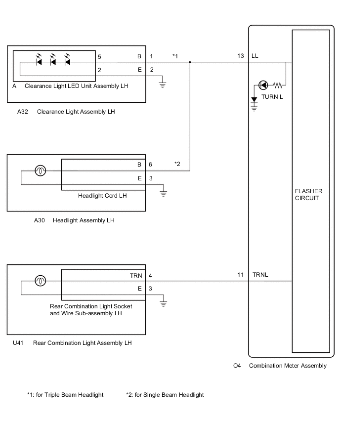
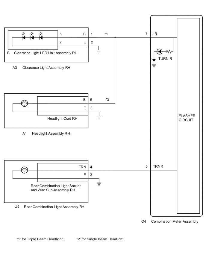
*1: for Triple Beam Headlight
-
*2: for Single Beam Headlight
WIRING DIAGRAM
-
FOR LH SIDE
-
FOR RH SIDE
CAUTION / NOTICE / HINT
Note
Inspect the turn signal light bulbs and sockets before performing the following procedure.
PROCEDURE
-
CHECK LIGHTS
-
Inspect the illumination of each turn signal light.
Result Result Proceed to Front turn signal light LH does not blink A Rear turn signal light LH does not blink B Front turn signal light RH does not blink C Rear turn signal light RH does not blink D
B 
CHECK HARNESS AND CONNECTOR (REAR COMBINATION LIGHT ASSEMBLY LH - COMBINATION METER ASSEMBLY AND BODY GROUND) Click here
C
CONFIRM MODEL Click here
D
CHECK HARNESS AND CONNECTOR (REAR COMBINATION LIGHT ASSEMBLY RH - COMBINATION METER ASSEMBLY AND BODY GROUND) Click here
A 
-
-
CONFIRM MODEL
-
Choose the model to be inspected.
Result Result Proceed to for Triple Beam Headlight A for Single Beam Headlight B
B
CHECK HARNESS AND CONNECTOR (HEADLIGHT ASSEMBLY LH - COMBINATION METER ASSEMBLY AND BODY GROUND) Click here
A
-
-
CHECK HARNESS AND CONNECTOR (CLEARANCE LIGHT ASSEMBLY LH - COMBINATION METER ASSEMBLY AND BODY GROUND)
-
Disconnect the A32 clearance light assembly LH connector.
-
Disconnect the O4 combination meter assembly connector.
-
Measure the resistance according to the value(s) in the table below.
Standard Resistance Tester Connection Condition Specified Condition A32-1 (B) - O4-13 (LL) Always Below 1 Ω A32-2 (E) - Body ground Always Below 1 Ω Result Proceed to OK NG
NG 
REPAIR OR REPLACE HARNESS OR CONNECTOR
OK
-
-
CHECK LH SIDE LIGHTS (COMBINATION METER ASSEMBLY)
-
Interchange the clearance light assembly LH with RH and connect the connectors.
-
Check that the front turn signal light operates normally.
OK Front turn signal light blinks. Result Proceed to OK NG
NG
REPLACE COMBINATION METER ASSEMBLY Click here
OK
-
-
INSPECT CLEARANCE LIGHT ASSEMBLY LH

*a Component without harness connected
(Clearance Light Assembly LH)
-
Remove the clearance light LED unit assembly LH from clearance light assembly LH.
-
Measure the resistance according to the value(s) in the table below.
Standard Resistance Tester Connection Condition Specified Condition A-5 - A32-1 (B) Always Below 1 Ω A-2 - A32-2 (E) Always Below 1 Ω Result Proceed to OK NG
OK
REPLACE CLEARANCE LIGHT LED UNIT ASSEMBLY LH Click here
NG
REPLACE CLEARANCE LIGHT ASSEMBLY LH Click here
-
-
CHECK HARNESS AND CONNECTOR (HEADLIGHT ASSEMBLY LH - COMBINATION METER ASSEMBLY AND BODY GROUND)
-
Disconnect the A30 headlight assembly LH connector.
-
Disconnect the O4 combination meter assembly connector.
-
Measure the resistance according to the value(s) in the table below.
Standard Resistance Tester Connection Condition Specified Condition A30-6 (B) - O4-13 (LL) Always Below 1 Ω A30-3 (E) - Body ground Always Below 1 Ω Result Proceed to OK NG
NG
REPAIR OR REPLACE HARNESS OR CONNECTOR
OK
-
-
CHECK LH SIDE LIGHTS (COMBINATION METER ASSEMBLY)
-
Interchange the headlight assembly LH with RH and connect the connectors.
-
Check that the front turn signal light operates normally.
OK Front turn signal light blinks. Result Proceed to OK NG
OK
REPLACE HEAD LIGHT CORD LH Click here
NG
REPLACE COMBINATION METER ASSEMBLY Click here
-
-
CHECK HARNESS AND CONNECTOR (REAR COMBINATION LIGHT ASSEMBLY LH - COMBINATION METER ASSEMBLY AND BODY GROUND)
-
Disconnect the U41 rear combination light assembly LH connector.
-
Disconnect the O4 combination meter assembly connector.
-
Measure the resistance according to the value(s) in the table below.
Standard Resistance Tester Connection Condition Specified Condition U41-4 (TRN) - O4-11 (TRNL) Always Below 1 Ω U41-3 (E) - Body ground Always Below 1 Ω Result Proceed to OK NG
NG
REPAIR OR REPLACE HARNESS OR CONNECTOR
OK
-
-
CHECK LH SIDE LIGHTS (COMBINATION METER ASSEMBLY)
-
Interchange the rear combination light assembly LH with RH and connect the connectors.
-
Check that the rear turn signal light operates normally.
OK Rear turn signal light blinks. Result Proceed to OK NG
OK
REPLACE REAR COMBINATION LIGHT SOCKET AND WIRE SUB-ASSEMBLY LH Click here
NG
REPLACE COMBINATION METER ASSEMBLY Click here
-
-
CONFIRM MODEL
-
Choose the model to be inspected.
Result Result Proceed to for Triple Beam Headlight A for Single Beam Headlight B
B
CHECK HARNESS AND CONNECTOR (HEADLIGHT ASSEMBLY RH - COMBINATION METER ASSEMBLY AND BODY GROUND) Click here
A
-
-
CHECK HARNESS AND CONNECTOR (CLEARANCE LIGHT ASSEMBLY RH - COMBINATION METER ASSEMBLY AND BODY GROUND)
-
Disconnect the A3 clearance light assembly RH connector.
-
Disconnect the O4 combination meter assembly connector.
-
Measure the resistance according to the value(s) in the table below.
Standard Resistance Tester Connection Condition Specified Condition A3-1 (B) - O4-7 (LR) Always Below 1 Ω A3-2 (E) - Body ground Always Below 1 Ω Result Proceed to OK NG
NG
REPAIR OR REPLACE HARNESS OR CONNECTOR
OK
-
-
CHECK RH SIDE LIGHTS (COMBINATION METER ASSEMBLY)
-
Interchange the clearance light assembly RH with LH and connect the connectors.
-
Check that the front turn signal light operates normally.
OK Front turn signal light blinks. Result Proceed to OK NG
NG
REPLACE COMBINATION METER ASSEMBLY Click here
OK
-
-
INSPECT CLEARANCE LAMP ASSEMBLY RH
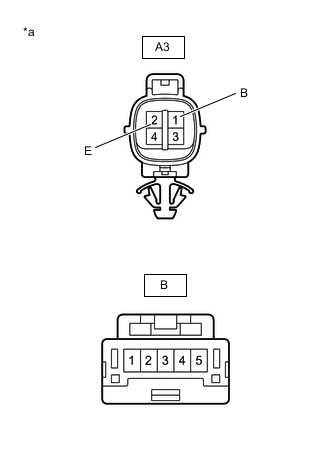
*a Component without harness connected
(Clearance Light Assembly RH)
-
Remove the clearance light LED unit assembly RH from clearance light assembly RH.
-
Measure the resistance according to the value(s) in the table below.
Standard Resistance Tester Connection Condition Specified Condition B-5 - A3-1 (B) Always Below 1 Ω B-2 - A3-2 (E) Always Below 1 Ω Result Proceed to OK NG
OK
REPLACE CLEARANCE LIGHT LED UNIT ASSEMBLY RH Click here
NG
REPLACE CLEARANCE LIGHT ASSEMBLY RH Click here
-
-
CHECK HARNESS AND CONNECTOR (HEADLIGHT ASSEMBLY RH - COMBINATION METER ASSEMBLY AND BODY GROUND)
-
Disconnect the A1 headlight assembly RH connector.
-
Disconnect the O4 combination meter assembly connector.
-
Measure the resistance according to the value(s) in the table below.
Standard Resistance Tester Connection Condition Specified Condition A1-6 (B) - O4-7 (LR) Always Below 1 Ω A1-3 (E) - Body ground Always Below 1 Ω Result Proceed to OK NG
NG
REPAIR OR REPLACE HARNESS OR CONNECTOR
OK
-
-
CHECK RH SIDE LIGHTS (COMBINATION METER ASSEMBLY)
-
Interchange the headlight assembly RH with LH and connect the connectors.
-
Check that the front turn signal light operates normally.
OK Front turn signal light blinks. Result Proceed to OK NG
OK
REPLACE HEAD LIGHT CORD RH Click here
NG
REPLACE COMBINATION METER ASSEMBLY Click here
-
-
CHECK HARNESS AND CONNECTOR (REAR COMBINATION LIGHT ASSEMBLY RH - COMBINATION METER ASSEMBLY AND BODY GROUND)
-
Disconnect the U5 rear combination light assembly RH connector.
-
Disconnect the O4 combination meter assembly connector.
-
Measure the resistance according to the value(s) in the table below.
Standard Resistance Tester Connection Condition Specified Condition U5-4 (TRN) - O4-5 (TRNR) Always Below 1 Ω U5-3 (E) - Body ground Always Below 1 Ω Result Proceed to OK NG
NG
REPAIR OR REPLACE HARNESS OR CONNECTOR
OK
-
-
CHECK RH SIDE LIGHTS (COMBINATION METER ASSEMBLY)
-
Interchange the rear combination light assembly RH with LH and connect the connectors.
-
Check that the rear turn signal light operates normally.
OK Rear turn signal light blinks. Result Proceed to OK NG
OK
REPLACE REAR COMBINATION LIGHT SOCKET AND WIRE SUB-ASSEMBLY RH Click here
NG
REPLACE COMBINATION METER ASSEMBLY Click here
-