METER / GAUGE SYSTEM, Diagnostic DTC:B150B
| DTC Code | DTC Name |
|---|---|
| B150B | Lost Communication with Gigabit Video Interface |
DESCRIPTION
The combination meter assembly receives an image information signal from the radio receiver assembly through a video signal (digital) line.
Based on this signal, audio and visual system or navigation system information is displayed on the multi-information display.
This DTC is stored when the combination meter assembly cannot receive the signal.
| DTC No. | Detection Item | DTC Detection Condition | Trouble Area | Memory | Note |
|---|---|---|---|---|---|
| B150B | Lost Communication with Gigabit Video Interface | After the combination meter assembly receives a registration information signal, which is sent by the radio receiver assembly when the engine switch is on (ACC), 1 or more times, and reception of the "Image ON" signal is confirmed, a GVIF video signal cannot be received for 3 second or more. |
|
DTC stored | w/ Navigation System |
WIRING DIAGRAM
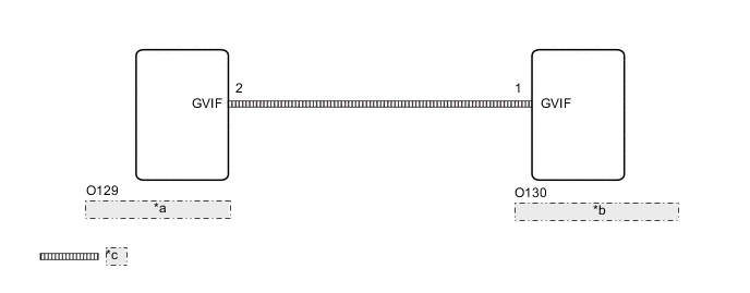
| *a | Radio Receiver Assembly |
| *b | Combination Meter Assembly |
| *c | Video Signal (Digital) |
CAUTION / NOTICE / HINT
Note
If DTCs B150B and B150A are output simultaneously, troubleshoot for B150A first.
PROCEDURE
-
CHECK FOR DTCs
-
Check if navigation system DTCs are not output.
Body Electrical > Navigation System > Trouble CodesOK Navigation system DTCs are not output. Result Proceed to OK NG
NG 
GO TO NAVIGATION SYSTEM Click here
OK 
-
-
REPLACE COMBINATION METER ASSEMBLY
-
Replace the combination meter assembly with a new or known good one.
-
Turn the engine switch on (IG) and wait 30 seconds.
Note
A maximum of 30 seconds is required to send/receive the registration information between the combination meter assembly and radio receiver assembly.
-
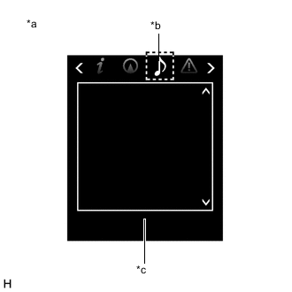
*a Multi-information Display *b Audio Tab *c Screen Operate the steering pad switch assembly and check that the audio tab illuminates.
Note
For TFT Meter Type, operate the steering pad switch assembly after moving the movable meter ring.
-
Check for DTCs and check the display status of the multi-information display.
Body Electrical > Combination Meter > Trouble CodesResult Result Proceed to The multi-information display screen is blank when selecting the audio tab while operating the steering pad switch assembly. A DTC B150B is output. The audio tab does not illuminate. B
-
The audio tab illuminates.
-
The audio display is shown on the multi-information display screen when selecting the audio tab while operating the steering pad switch assembly.
-
DTC B150B is not output.
C -
B
GO TO DTC B150A Click here
C
END
A
-
-
REPLACE RADIO RECEIVER ASSEMBLY
-
Replace the radio receiver assembly with a new or known good one.
-
Turn the engine switch on (IG) and wait 30 seconds.
Note
A maximum of 30 seconds is required to send/receive the registration information between the combination meter assembly and radio receiver assembly.
-

*a Multi-information Display *b Audio Tab *c Screen Operate the steering pad switch assembly and check that the audio tab illuminates.
Note
For TFT Meter Type, operate the steering pad switch assembly after moving the movable meter ring.
-
Check for DTCs and check the display status of the multi-information display.
Body Electrical > Combination Meter > Trouble CodesResult Result Proceed to
-
The audio tab illuminates.
-
The audio display is shown on the multi-information display screen when selecting the audio tab while operating the steering pad switch assembly.
-
DTC B150B is not output.
A The audio tab does not illuminate. B The multi-information display screen is blank when selecting the audio tab while operating the steering pad switch assembly. C DTC B150B is output. -
A
END
B
GO TO DTC B150A Click here
C
REPAIR OR REPLACE HARNESS OR CONNECTOR
-