METER / GAUGE SYSTEM SYSTEM DESCRIPTION
-
OUTLINE OF COMBINATION METER ASSEMBLY
-
for Optitron Meter Type
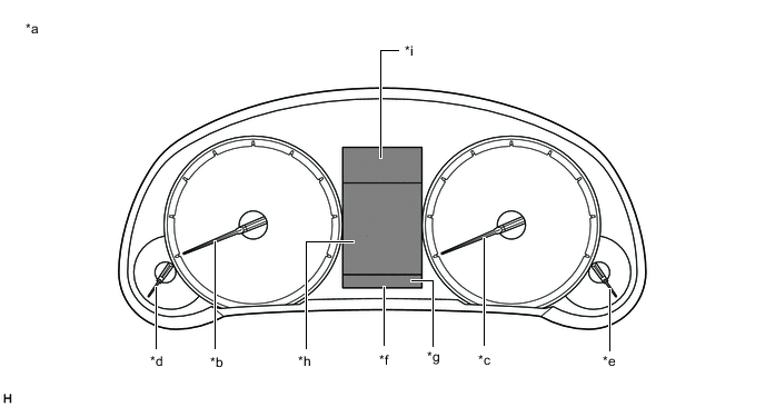
*a Indication Example *b Tachometer *c Speedometer *d Engine Coolant Temperature Receiver Gauge *e Fuel Receiver Gauge *f Multi-information Display *g Display Area A1 *h Display Area A2 *i Display Area A3 - - -
for TFT Meter Type
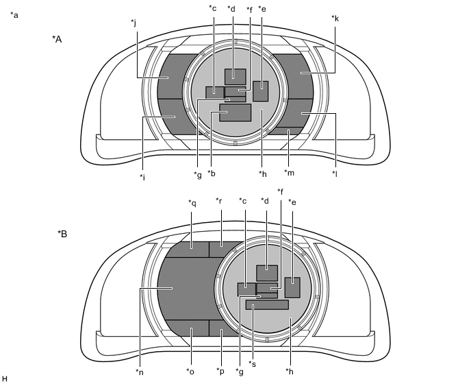
*A Movable Meter Ring not Activated *B Movable Meter Ring Activated *a Indication Example *b Display Area B1 *c Display Area B2 *d Display Area B3 *e Display Area B4 *f Display Area B5 *g Display Area B6 *h Display Area B7 *i Display Area B8 *j Display Area B9 *k Display Area B10 *l Display Area B11 *m Display Area B12 *n Display Area B13 *o Display Area B14 *p Display Area B15 *q Display Area B16 *r Display Area B17 *s Display Area B18 - -
-
-
INPUT AND OUTPUT SIGNALS OF COMBINATION METER ASSEMBLY
-
Meter or Gauge
Item Condition Input/Output Communication line Signal Component Display Area Speedometer
-
Gauge*1
-
Displayed*2
Input CAN Vehicle speed (SP1) signal Brake actuator assembly (Skid control ECU) B3 - Direct line Vehicle speed pulse input signal Output CAN Vehicle speed signal (meter to other) Related ECUs Speed tolerance A signal
-
Driving support ECU assembly*5
-
Lane departure warning camera*6
Speed tolerance B signal Direct line Vehicle speed pulse output signal Related ECUs Tachometer
-
Gauge*1
-
Displayed*2
Input CAN Engine RPM data signal ECM B7 Fuel receiver gauge
-
Gauge*1
-
Displayed*2
Input CAN Fuel consumption signal ECM B10, B14 Engine RPM data signal Starter signal Shift position P signal Shift position R signal Shift position N signal Shift position D signal Mode indicator signal Vehicle speed (SP1) signal Brake actuator assembly (Skid control ECU) Direct line Fuel level signal
-
Fuel sender gauge assembly
-
No. 2 fuel sender gauge assembly
Output CAN Fuel gauge state signal
-
DCM (Telematics transceiver)*4
-
Radio receiver assembly*3
Fuel gauge initial signal Fuel direct data signal DCM (Telematics transceiver)*4 Fuel initial signal Fuel average signal Fuel consumption scale signal Radio receiver assembly*3 Engine coolant temperature receiver gauge
-
Gauge*1
-
Displayed*2
Input CAN Engine coolant temperature signal ECM B9, B16
-
*1: for Optitron Meter Type
-
*2: for TFT Meter Type
-
*3: w/ Navigation System
-
*4: w/ Manual (SOS) Switch
-
*5: w/ Pre-crash Safety System
-
*6: w/ Lane Departure Alert System
-
-
Warning or Indicator
Item Condition Input/Output Communication line Signal Component Master warning light Comes on/Blinks Input CAN/Direct line Each warning signal Related ECUs Door open warning light Comes on Input CAN Driver door courtesy switch signal Main body ECU (Multiplex network body ECU) Front passenger door courtesy switch signal Luggage courtesy switch signal Brake warning light Comes on Input CAN Brake warning light control flag signal Brake actuator assembly (Skid control ECU) Parking brake switch signal Main body ECU (Multiplex network body ECU) Direct line Brake fluid level warning switch signal Brake master cylinder reservoir assembly (Brake fluid level warning switch) Driver or front passenger seat belt warning light Comes on/Blinks Input CAN Driver seat belt buckle switch signal Main body ECU (Multiplex network body ECU) Parking brake switch signal Shift position P signal ECM Vehicle speed (SP1) signal Brake actuator assembly (Skid control ECU) Direct line Front passenger seat belt buckle switch detection status signal Front seat inner belt assembly Front passenger seat occupant detection status signal Separate type front seat cushion pad (Occupant detection sensor) SRS warning light Comes on Input CAN Airbag warning light control request signal Airbag sensor assembly Test mode signal ECM Charge warning light Comes on Input CAN Charge light indicator signal ECM Direct line Charge L terminal signal Generator assembly EPS warning light Comes on/Blinks Input CAN EPS warning light request signal Power steering ECU assembly MIL (Check engine warning light) Comes on/Blinks Input CAN MIL request signal ECM PCS warning light*1 Comes on/Blinks Input CAN PCS indicator display signal Driving support ECU assembly Slip indicator light Comes on/Blinks Input CAN Slip indicator light signal Brake actuator assembly (Skid control ECU) VSC OFF indicator light Comes on Input CAN VSC OFF light signal Brake actuator assembly (Skid control ECU) ABS warning light Comes on/Blinks Input CAN ABS warning light control flag signal Brake actuator assembly (Skid control ECU) Tire pressure warning light*12 Comes on/Blinks Input CAN TPMS warning indicator condition 1 signal Main body ECU (Multiplex network body ECU) Fuel level warning light Comes on Input Direct line Fuel level signal Fuel sender gauge assembly No. 2 fuel sender gauge assembly Rear fog indicator light*9 Comes on Input CAN Rear fog light request signal Main body ECU (Multiplex network body ECU) Headlight leveling indicator light Comes on Input CAN Starter signal ECM Headlight leveling indicator signal Headlight leveling ECU assembly*13 Headlight control ECU sub-assembly LH*14 Automatic high beam indicator light*2 Comes on Input CAN Smart Beam indicator signal Main body ECU (Multiplex network body ECU) Lane departure alert indicator light*3, *4 Comes on Input CAN Indicator display signal Lane departure warning camera Cruise control indicator light*3, *5 Comes on Input CAN Cruise main indicator signal ECM Cruise control warning signal Cruise control indicator light (Constant speed control mode)*3, *6 Comes on Input CAN Following distance time signal Driving support ECU assembly Cruise control warning signal Cruise operation indicator signal Cruise control indicator light (Vehicle-to-vehicle distance control mode)*3, *6 Comes on Input CAN Following distance time signal Driving support ECU assembly Cruise control warning signal Cruise operation indicator signal High beam indicator light Comes on Input CAN High beam headlight request signal Main body ECU (Multiplex network body ECU) Tail indicator light*13 Comes on Input CAN Taillight request signal Main body ECU (Multiplex network body ECU) Front fog indicator light*7 Comes on Input CAN Front fog light request signal Main body ECU (Multiplex network body ECU) Turn indicator light Blinks Input Direct line LH turn signal switch signal Windshield wiper switch assembly RH turn signal switch signal Hazard warning switch signal Air conditioner control assembly (Hazard warning signal switch) CAN Hazard light activation request signal DCM (Telematics transceiver) - Output CAN Turn light state signal Blind spot monitor sensor LH Driving support ECU assembly Lane departure warning camera Hazard switch state signal Radio receiver assembly*10 DCM (Telematics transceiver)*11 Brake actuator assembly (Skid control ECU) Direct line LH turn signal switch signal Each turn signal light RH turn signal switch signal Hazard warning switch signal Eco driving indicator light Comes on Input CAN Ecology light indicator signal ECM Cruise SET indicator light*3, *5 Comes on Input CAN Cruise set indicator signal ECM Cruise SET indicator light*3, *6 Comes on Input CAN Cruise set indicator signal Driving support ECU assembly Clearance sonar indicator light*8 Comes on Input CAN CLSO main switch indicator turn ON signal Clearance warning ECU assembly Rear seat belt warning light*15 Comes on Input CAN Driver door courtesy switch signal Main body ECU (Multiplex network body ECU) Front passenger door courtesy switch signal Vehicle speed (SP1) signal Brake actuator assembly (Skid control ECU) Direct line Rear left seat belt buckle switch signal No. 1 rear seat inner belt assembly LH Rear right seat belt buckle switch signal Rear seat inner belt assembly Output Direct line Rear right seat belt warning output signal Air conditioner control assembly Rear left seat belt warning output signal
-
*1: w/ Pre-crash Safety System
-
*2: w/ Automatic High Beam System
-
*3: for TFT Meter Type
-
*4: w/ Lane Departure Alert System
-
*5: w/o Dynamic Radar Cruise Control System
-
*6: w/ Dynamic Radar Cruise Control System
-
*7: w/ Front Fog Light
-
*8: w/ LEXUS Parking Assist-sensor System
-
*9: w/ Rear Fog Light
-
*10: w/ Navigation System
-
*11: w/ Manual (SOS) Switch
-
*12: w/ Tire Pressure Warning System
-
*13: for Single Beam Headlight
-
*14: for Triple Beam Headlight
-
*15: w/ Rear Seat Belt Warning
-
-
Multi-information Display
Item Condition Input/Output Communication line Signal Component Display Area Opening - - - - - A1, A2, A3, B7 Ending - - - - - B7 ODO meter Displayed Input CAN Vehicle speed pulse signal integrated value signal Brake actuator assembly (Skid control ECU) A1, B11, B18 Vehicle speed (SP1) signal Direct line ODO/TRIP change switch signal Trip switch - Output CAN Odo meter unit signal Related ECUs Odo meter signal TRIP meter Displayed Input CAN Vehicle speed pulse signal integrated value signal Brake actuator assembly (Skid control ECU) A1, B11, B18 Vehicle speed (SP1) signal Direct line ODO/TRIP change switch signal Trip switch - Output CAN TRIP A signal DCM (Telematics transceiver)*16 TRIP B signal Current fuel consumption (Bar type) Displayed Input CAN ACC switch signal Main body ECU (Multiplex network body ECU) A2, B1, B13 Vehicle speed (SP1) signal Brake actuator assembly (Skid control ECU) Fuel consumption signal ECM Engine RPM data signal - Output CAN Drive monitor unit signal 0 Radio receiver assembly*9 Drive monitor display signal (Current fuel consumption) Average fuel consumption (After reset) Displayed Input CAN Engine RPM data signal ECM A2, B1, B13 Fuel consumption signal Vehicle speed (SP1) signal Brake actuator assembly (Skid control ECU) Vehicle speed pulse signal integrated value signal Direct line Reset signal Steering pad switch assembly - Output CAN Drive monitor unit signal 6 Radio receiver assembly*9 Drive monitor display signal (Total average fuel consumption) Average fuel consumption (After start) Displayed Input CAN Engine RPM data signal ECM A2, B1, B13 Fuel consumption signal Vehicle speed (SP1) signal Brake actuator assembly (Skid control ECU) Vehicle speed pulse signal integrated value signal Average fuel consumption (After refuel) Displayed Input CAN Engine RPM data signal ECM A2, B1, B13 Fuel consumption signal Vehicle speed (SP1) signal Brake actuator assembly (Skid control ECU) Vehicle speed pulse signal integrated value signal - Output Drive monitor display signal (Average fuel consumption after refuel) Radio receiver assembly*9 Average speed (After reset) Displayed Input CAN Engine RPM data signal ECM A2, B1, B13 Vehicle speed (SP1) signal Brake actuator assembly (Skid control ECU) Vehicle speed pulse signal integrated value signal Direct line Reset signal Steering pad switch assembly Average speed (After start) Displayed Input CAN Engine RPM data signal ECM A2, B1, B13 Vehicle speed (SP1) signal Brake actuator assembly (Skid control ECU) Vehicle speed pulse signal integrated value signal - Output Drive monitor unit signal 1 Radio receiver assembly*9 Drive monitor display signal (After starting average speed) Elapsed time (After reset) Displayed Input CAN Engine RPM data signal ECM A2, B1, B13 Direct line Reset signal Steering pad switch assembly Elapsed time (After start) Displayed Input CAN Engine RPM data signal ECM A2, B1, B13 - Output Drive monitor display signal (After starting driving time) Radio receiver assembly*9 Distance (Range) Displayed Input CAN Engine type information 1 signal ECM A2, B1, B13 Engine type information 2 signal Engine type information 3 signal Engine type information 4 signal Engine RPM data signal Drivetrain information signal Fuel consumption signal Vehicle speed pulse signal integrated value signal Brake actuator assembly (Skid control ECU) Direct line Fuel level signal Fuel sender gauge assembly No. 2 fuel sender gauge assembly - Output CAN Drive monitor unit signal 4 Radio receiver assembly*9 Drive monitor display signal (Drivable distance) Distance (After start) Displayed Input CAN Engine RPM data signal ECM A2, B1, B13 Vehicle speed (SP1) signal Brake actuator assembly (Skid control ECU) Vehicle speed pulse signal integrated value signal Eco driving indicator zone Displayed Input CAN Eco-zone indicator level signal ECM A2, B1, B13 Other (Blank) - - - - - A2, B1, B13 Tire pressure*24 Displayed Input CAN TPMS FL (ID1) tire pressure information signal Main body ECU (Multiplex network body ECU) A2, B1, B13 TPMS FR (ID2) tire pressure information signal TPMS RL (ID3) tire pressure information signal TPMS RR (ID4) tire pressure information signal TPMS SP (ID5) tire pressure information signal TPMS FL (ID1) tire indicator information 0 signal TPMS FR (ID2) tire indicator information 0 signal TPMS RL (ID3) tire indicator information 0 signal TPMS RR (ID4) tire indicator information 0 signal TPMS SP (ID5) tire indicator information 0 signal TPMS indicator number information 0 signal TPMS unit information 0 signal TPMS display request bit 0 signal TPMS variation signal Gear position Displayed Input CAN Transmission information signal ECM A2, B1, B13 Actual shift gear indicator signal Gear information signal Shift position P signal Shift position R signal Shift position N signal Shift position D signal Shift gear signal Mode indicator signal Sports mode enable signal Transmission oil temperature range signal Drive information tab Displayed - - - - A2, B13 Navigation tab*9 Displayed Input CAN/Local bus/GVIF*9 Navigation signal Radio receiver assembly A2, B13 Audio tab Displayed Input CAN/Local bus/GVIF*9 Audio signal Radio receiver assembly A2, B13 Cruise control operation guide tab*4 Displayed Input CAN Indicator display signal Driving support ECU assembly A2, B13 Lane departure alert tab*3, *6 Displayed Input CAN Indicator display signal Lane departure warning camera A2, B13 Message tab Displayed - - - - A2, B13 Setting tab Displayed - - - - A2, B13 Shift position Displayed Input CAN Shift position P signal ECM A3, B5 Shift position R signal Shift position N signal Shift position D signal Shift gear signal Mode indicator signal Sports mode enable signal Transmission oil temperature range signal GEAR shift indicator Displayed Input CAN Shift up signal ECM A3, B5 Shift down signal SPORT indicator*15 Displayed Input CAN Integrated sport mode indicator ECM A3, B6 SPORT S indicator*10 Displayed Input CAN Integrated sport mode signal ECM A3, B6 SPORT S+ indicator*10 Displayed Input CAN AVS (TEMS) light signal Absorber control ECU A3, B6 Integrated sport mode signal ECM ECO indicator Displayed Input CAN Eco mode indicator signal ECM A3, B6 SNOW indicator Displayed Input CAN ECT SNOW indicator signal ECM A3, B2 Cruise SET indicator light*1, *3 Displayed Input CAN Cruise set indicator signal ECM A3 Cruise SET indicator light*1, *4 Displayed Input CAN Cruise set indicator signal Driving support ECU assembly A3 Cruise control indicator light*1, *3 Displayed Input CAN Cruise main indicator signal ECM A3 Cruise control warning signal Cruise control indicator light (Constant speed control mode)*1, *4 Displayed Input CAN Following distance time signal Driving support ECU assembly A3 Cruise control warning signal CRUISE operation indicator signal Cruise control indicator light (Vehicle-to-vehicle distance control mode)*1, *4 Displayed Input CAN Following distance time signal Driving support ECU assembly A3 Cruise control warning signal CRUISE operation indicator signal Lane departure alert indicator light*1, *6 Displayed Input CAN Indicator display signal Lane departure warning camera A3 Outside temperature Displayed Input CAN Ambient temperature display signal Air conditioning amplifier assembly A3, B8, B17 Switch signal of 0 or 0.5 below decimal point of ambient temperature display signal Icy Street warning Displayed Input CAN Ambient temperature display signal Air conditioning amplifier assembly A3, B8, B17 Switch signal of 0 or 0.5 below decimal point of ambient temperature display signal Phone (Received Call)*9 Displayed Input CAN/Local bus/GVIF*9 Phone (Received call) signal Radio receiver assembly A2, B1, B13 Turn-by-turn Navigation*9 Displayed Input CAN/Local bus/GVIF*9 Turn-by-turn signal Radio receiver assembly A2, B1, B13 Vehicle speed indicator*2 Displayed Input CAN Vehicle speed (SP1) signal Brake actuator assembly (Skid control ECU) B5 REV indicator*2 Displayed Input CAN Engine RPM data signal ECM B7 REV peak*2 Displayed Input CAN Engine RPM data signal ECM B7 Movable meter ring operation guide*2 Displayed - - - - B11 Light control switch guide*27 Displayed Input CAN Taillight request signal Main body ECU (Multiplex network body ECU) A2, B8, B13 Front fog light request signal*19 Rear fog light request signal*20 LIN Distinction signal of wiper right/left Windshield wiper switch assembly Wiper switch guide*27 Displayed Input LIN Volume signal for wiper adjustment signal Windshield wiper switch assembly A2, B11, B13 Auto position signal of wiper switch signal AUTO mode cancellation signal Distinction signal of wiper right/left signal Momentary switch HI position recognition signal Momentary switch WPUP position recognition signal Momentary switch AUTO position recognition signal Cruise control main switch guide*4 Displayed Input CAN Following distance time signal Driving support ECU assembly A2, B8, B13 Control vehicle speed signal Cruise set indicator signal Cruise control warning signal Cruise operation indicator signal Radar cruise warning signal Cruise control set/coast switch signal Cruise control resume/accelerate switch signal Cruise control cancel switch signal ACCESSORY Displayed Input CAN Display request of vehicle mode signal Certification ECU (Smart key ECU assembly) A1, B12, B15 IGNITION ON Displayed Input CAN Display request of vehicle mode signal Certification ECU (Smart key ECU assembly) A1, B12, B15 VGRS Test Mode*12 Displayed Input CAN Demand signal to meter Front steering control ECU A2, B1, B13 DRS Test Mode*17 Displayed Input CAN Demand signal to meter Rear steering control ECU A2, B1, B13 Adjusting LDA Camera*6 Displayed Input CAN Camera adjustment mode text display signal Lane departure warning camera A2, B1, B13 Adjusting Front Radar Beam*4 Displayed Input CAN Inspection mode for ACC signal Driving support ECU assembly A2, B1, B13 BRAKE!*5 Displayed Input CAN PCS warning message signal Driving support ECU assembly A2, B1, B13 Holding in Engine Switch Will Cause an Emergency Engine Stop. Displayed Input CAN Smart system warning 2 signal Certification ECU (Smart key ECU assembly) A2, B1, B13 To Restart Car, Shift Lever to "N" and Press Engine Switch. Displayed Input CAN Smart system warning 2 signal Certification ECU (Smart key ECU assembly) A2, B1, B13 The Engine Has Stopped. Please Put Shift Lever into "P". Displayed Input CAN Engine RPM data signal ECM A2, B1, B13 Shift position P signal Shift position N signal Vehicle speed (SP1) signal Brake actuator assembly (Skid control ECU) The Engine Has Stopped. Please Stop Your Car in a Safe Place. Displayed Input CAN Engine RPM data signal ECM A2, B1, B13 Shift position P signal Shift position N signal Vehicle speed (SP1) signal Brake actuator assembly (Skid control ECU) Dynamic radar cruise control*4 or Lane departure alert*6 warning reminder indicator Displayed Input CAN ACC display ID 1 signal Driving support ECU assembly A2, B1, B13 ACC display ID 2 signal Control vehicle speed signal Control vehicle speed unit signal White line symbol left side signal Lane departure warning camera White line symbol right side signal Brake Malfunction Displayed Input CAN Brake warning light control flag signal Brake actuator assembly (Skid control ECU) A2, B1, B13 The Accelerator is Stuck. Please Depress Brake Pedal to Stop Car. Displayed Input CAN BOS multi-information request signal ECM A2, B1, B13 Each door ajar Displayed Input CAN Driver door courtesy switch signal Main body ECU (Multiplex network body ECU) A2, B4 Front passenger door courtesy switch signal Luggage courtesy switch signal Hood courtesy switch signal Steering wheel signal Vehicle speed (SP1) signal Brake actuator assembly (Skid control ECU) Clearance sonar detection (image display)*8 Displayed Input CAN Clearance sonar main switch indicator turn ON signal Clearance warning ECU assembly A2, B4 Cluster indicator turn ON request signal Front center area information signal Front left area information signal Front right area information signal Rear center area information signal Rear left area information signal Rear right area information signal Sensor diag request signal Check Park Sonar System*8 Displayed Input CAN Sensor diag request signal Clearance warning ECU assembly A2, B1, B13 Clean Park Sonar*8 Displayed Input CAN Sensor diag request signal Clearance warning ECU assembly A2, B1, B13 Auto Power OFF to Conserve Battery Displayed Input CAN Smart system warning 2 signal Certification ECU (Smart key ECU assembly) A2, B1, B13 Shift to P position when parked Displayed Input CAN Smart system warning 2 signal Certification ECU (Smart key ECU assembly) A2, B1, B13 EPS Failure. Steering Wheel Harder to Turn. Displayed Input CAN Multi-information request signal Power steering ECU assembly A2, B1, B13 Voltage Abnormality. Steering Wheel Harder to Turn. Displayed Input CAN Multi-information request signal Power steering ECU assembly A2, B1, B13 Check Power Steering System Displayed Input CAN Multi-information request signal Power steering ECU assembly A2, B1, B13 Release Parking Brake Displayed Input CAN Parking brake switch signal Main body ECU (Multiplex network body ECU) A2, B1, B13 Vehicle speed (SP1) signal Brake actuator assembly (Skid control ECU) A2, B1, B13 Key not detected Displayed Input CAN Smart system warning 1 signal Certification ECU (Smart key ECU assembly) A2, B1, B13 1st Gear not available due to slippery road surface Displayed Input CAN Reject flag of range for low gear signal ECM A2, B1, B13 Speed Limit Exceeded*11 Displayed Input CAN Vehicle speed (SP1) signal Brake actuator assembly (Skid control ECU) A2, B1, B13 Check SRS Airbag System Displayed Input CAN SRS warning light control request signal Airbag sensor assembly A2, B1, B13 Check ABS Displayed Input CAN ABS warning light control flag signal Brake actuator assembly (Skid control ECU) A2, B1, B13 Engine Coolant High Temperature Displayed Input CAN Engine coolant temperature signal ECM A2, B1, B13 Clean Radar Sensor*4 Displayed Input CAN Cruise control warning signal Driving support ECU assembly A2, B1, B13 Detection of dirt adhesion on sensor signal Cruise Control not available*4 Displayed Input CAN Cruise control warning signal Driving support ECU assembly A2, B1, B13 Detection of dirt adhesion on sensor signal Bad weather detection signal LDA not available*6 Displayed Input CAN Temporary unusable condition text display signal Lane departure warning camera A2, B1, B13 Check Entry & Start System Displayed Input CAN Smart system warning 1 signal Certification ECU (Smart key ECU assembly) A2, B1, B13 BSM not available*13 Displayed Input CAN BSD module status signal Blind spot monitor sensor LH A2, B1, B13 Check Cruise Control System*4 Displayed Input CAN Cruise control warning signal Driving support ECU assembly A2, B1, B13 Check Cruise Control System*3 Displayed Input CAN Cruise control warning signal ECM A2, B1, B13 Check LDA System*6 Displayed Input CAN Fault condition text display signal Lane departure warning camera A2, B1, B13 Check PCS System*5 Displayed Input CAN PCS fault condition text display signal Driving support ECU assembly A2, B1, B13 Check BSM System*13 Displayed Input CAN BSD module status signal Blind spot monitor sensor LH A2, B1, B13 Engine Oil Pressure Low Displayed Input Direct line Engine oil pressure signal Engine oil pressure switch assembly A2, B1, B13 Transmission Fluid High Temperature Displayed Input CAN AT oil temperature warning signal ECM A2, B1, B13 Check VGRS System*12 Displayed Input CAN Demand signal to meter Front steering control ECU A2, B1, B13 Check DRS System*17 Displayed Input CAN Demand signal to meter Rear steering control ECU A2, B1, B13 POP UP HOOD Activated.*18 Displayed Input CAN Pedestrian protection system warning light ON request signal Airbag sensor assembly A2, B1, B13 POP UP HOOD Failure.*18 Displayed Input CAN Pedestrian protection system warning light ON request signal Airbag sensor assembly A2, B1, B13 LDA System is Unavailable Below 50 km/h.*6 Displayed Input CAN Speed condition failure text display signal Lane departure warning camera A2, B1, B13 LDA System is Unavailable at this Speed.*6 Displayed Input CAN Speed condition failure text display signal Lane departure warning camera A2, B1, B13 Dynamic radar cruise control*4 or Lane departure alert*6 indicator Displayed Input CAN ACC display ID 1 signal Driving support ECU assembly A2, B1, B13 ACC display ID 2 signal Control vehicle speed signal Control vehicle speed unit signal White line symbol left side signal Lane departure warning camera White line symbol right side signal Engine Stopped, Steering Wheel Harder to Turn. Displayed Input CAN Multi-information request signal Power steering ECU assembly A2, B1, B13 Turn Power OFF Displayed Input CAN Smart system warning 2 signal Certification ECU (Smart key ECU assembly) A2, B1, B13 Key detected in vehicle Displayed Input CAN Smart system warning 3 signal Certification ECU (Smart key ECU assembly) A2, B1, B13 Turn Light Off*21 Displayed Input CAN Driver door courtesy switch signal Main body ECU (Multiplex network body ECU) A2, B1, B13 Lighting system state signal Moon Roof opened*14 Displayed Input CAN Sliding roof open warning request signal Main body ECU (Multiplex network body ECU) A2, B1, B13 Window opened Displayed Input CAN Power window open warning request signal Main body ECU (Multiplex network body ECU) A2, B1, B13 Window / Moon Roof opened*14 Displayed Input CAN Power window open warning request signal Main body ECU (Multiplex network body ECU) A2, B1, B13 Sliding roof open warning request signal Depress brake pedal, touch engine switch with key Displayed Input CAN Smart system warning 1 signal Certification ECU (Smart key ECU assembly) A2, B1, B13 Depress brake pedal and push engine switch to start Displayed Input CAN Smart system warning 3 signal Certification ECU (Smart key ECU assembly) A2, B1, B13 The Accelerator is Stuck. Please Check the Accelerator. Displayed Input CAN BOS multi-information request signal ECM A2, B1, B13 Steering Lock active Displayed Input CAN Smart system warning 1 signal Certification ECU (Smart key ECU assembly) A2, B1, B13 Brake Override System Failure. Displayed Input CAN BOS multi-information request signal ECM A2, B1, B13 Key Battery Low Displayed Input CAN Smart system warning 1 signal Certification ECU (Smart key ECU assembly) A2, B1, B13 Engine Oil Level Low Displayed Input CAN Engine coolant temperature signal ECM A2, B1, B13 Direct line Engine oil level signal Engine oil level sensor Check Headlight System Displayed Input CAN Smart beam indicator signal*7 Main body ECU (Multiplex network body ECU) A2, B1, B13 LED headlight indicator signal*25 LED headlight indicator signal Headlight control ECU sub-assembly LH*26 Headlight leveling indicator signal Headlight leveling ECU assembly*25 Headlight control ECU sub-assembly LH*26 Starter signal ECM Both Accelerator and Brake Pedals Are Depressed. Displayed Input CAN BOS multi-information request signal ECM A2, B1, B13 Tire pressure indicator*23 Displayed Input CAN TPMS display request bit 0 signal Main body ECU (Multiplex network body ECU) A2, B1, B13 Check VGRS System*12 Displayed Input CAN Demand signal to meter Front steering control ECU A2, B1, B13 Check DRS System*17 Displayed Input CAN Demand signal to meter Rear steering control ECU A2, B1, B13 Washer Fluid Low Displayed Input Direct line Washer fluid level signal Level warning switch assembly A2, B1, B13 Fuel Low Displayed Input Direct line Fuel level signal Fuel sender gauge assembly A2, B1, B13 No. 2 fuel sender gauge assembly TRC OFF Displayed Input CAN TRAC OFF light signal Brake actuator assembly (Skid control ECU) A2, B1, B13 Starter signal ECM Injector Maintenance required soon*22 Displayed Input CAN Injector change indicator signal ECM A2, B1, B13 Injector Maintenance required*22 Displayed Input CAN Injector change indicator signal ECM A2, B1, B13 Turn on the high beam to activate AHB System*7 Displayed Input CAN Smart beam advice signal Main body ECU (Multiplex network body ECU) A2, B1, B13 Depress brake pedal and push engine switch to start Displayed Input CAN Smart system warning 1 signal Certification ECU (Smart key ECU assembly) A2, B1, B13 VSC System Switched Off. Pre-Crash Brake System Disengaged.*5 Displayed Input CAN PB temporary unusable condition text display signal Driving support ECU assembly A2, B1, B13 VSC OFF light signal Brake actuator assembly (Skid control ECU) PCS temporarily not available*5 Displayed Input CAN PCS temporary unusable condition text display signal Driving support ECU assembly A2, B1, B13 Operation of Electrical Items Restricted. Displayed Input CAN A/C load limitation warning signal Air conditioning amplifier assembly A2, B1, B13 Theft Sensor OFF*23 Displayed Input CAN Invasion sensor state display signal Main body ECU (Multiplex network body ECU) A2, B1, B13 Theft Sensor ON*23 Displayed Input CAN Invasion sensor state display signal Main body ECU (Multiplex network body ECU) A2, B1, B13
-
*1: for Optitron Meter Type
-
*2: for TFT Meter Type
-
*3: w/o Dynamic Radar Cruise Control System
-
*4: w/ Dynamic Radar Cruise Control System
-
*5: w/ Pre-crash Safety System
-
*6: w/ Lane Departure Alert System
-
*7: w/ Automatic High Beam System
-
*8: w/ LEXUS Parking Assist-sensor System
-
*9: w/ Navigation System
-
*10: w/ Adaptive Variable Suspension System
-
*11: w/ 120 km/h Speed Warning
-
*12: w/ Variable Gear Ratio Steering System
-
*13: w/ Blind Spot Monitor System
-
*14: w/ Sliding Roof System
-
*15: w/o Adaptive Variable Suspension System
-
*16: w/ Manual (SOS) Switch
-
*17: w/ Dynamic Rear Steering System
-
*18: w/ Pop Up Hood
-
*19: w/ Front Fog Light
-
*20: w/ Rear Fog Light
-
*21: w/ Light Reminder Warning
-
*22: w/ Injector Maintenance Required Reminder
-
*23: w/ Intrusion Sensor
-
*24: w/ Tire Pressure Warning System
-
*25: for Single Beam Headlight
-
*26: for Triple Beam Headlight
-
*27: w/ Auto Wiper System
-
-
Buzzer
Item Condition Input/Output Communication line Signal Component Seat belt warning (for Driver side) buzzer Sounds once/Sounds intermittently Input CAN Driver seat buckle switch signal Main body ECU (Multiplex network body ECU) Parking brake switch signal Shift position P signal ECM Shift position R signal Restart while driving notification buzzer Sounds continuously Input CAN Smart system warning 2 signal Certification ECU (Smart key ECU assembly) Engine switch operation while driving warning buzzer Sounds intermittently Input CAN SW operation buzzer intermittent request signal Certification ECU (Smart key ECU assembly) Seat belt warning (for Front passenger side) buzzer Sounds once/Sounds intermittently Input Direct line Front passenger seat belt buckle switch detection status signal Front seat inner belt assembly Front passenger seat occupant detection status signal Separate type front seat cushion pad (Occupant detection sensor) CAN Parking brake switch signal Main body ECU (Multiplex network body ECU) Shift position P signal ECM Shift position R signal Seat belt warning (for rear seat) buzzer*4 Sounds intermittently Input CAN Parking brake switch signal Main body ECU (Multiplex network body ECU) Driver door courtesy switch signal Front passenger door courtesy switch signal Vehicle speed (SP1) signal Brake actuator assembly (Skid control ECU) Shift position P signal ECM Shift position R signal Direct line Rear left seat belt buckle switch signal No. 1 rear seat inner belt assembly LH Rear right seat belt buckle switch signal Rear seat inner belt assembly Vehicle roll-away notification (STEP 1) buzzer Sounds continuously Input CAN Engine RPM data signal ECM Shift position P signal Shift position N signal Vehicle speed (SP1) signal Brake actuator assembly (Skid control ECU) Vehicle roll-away notification (STEP 2) buzzer Sounds intermittently Input CAN Engine RPM data signal ECM Shift position P signal Shift position N signal Vehicle speed (SP1) signal Brake actuator assembly (Skid control ECU) Brake fluid low warning buzzer Sounds intermittently Input CAN Vehicle speed (SP1) signal Brake actuator assembly (Skid control ECU) Direct line Brake fluid level warning switch signal Brake master cylinder reservoir assembly (Brake fluid level warning switch) Oil pressure warning buzzer Sounds intermittently Input CAN Engine RPM data signal ECM Vehicle speed (SP1) signal Brake actuator assembly (Skid control ECU) Direct line Engine oil pressure signal Engine oil pressure switch assembly EPS warning buzzer Sounds once Input CAN Demand buzzer to meter signal Power steering ECU assembly Engine coolant temperature warning buzzer Sounds once Input CAN Engine coolant temperature signal ECM Smart key warning buzzer Sounds intermittently Input CAN Meter buzzer intermittence request signal Certification ECU (Smart key ECU assembly) Sounds intermittently (Maximum 9 times) Input CAN Meter buzzer intermittent request (0.7 sec. cycle) signal Sounds once Input CAN Meter buzzer single-shot request signal Sounds continuously Input CAN Meter buzzer continuation request signal Lane departure alert warning buzzer*2 Sounds intermittently Input CAN LDW buzzer signal Lane departure warning camera Multi-information display warning buzzer Sounds once Input CAN Multi-information display warning signal Related ECUs Direct line Radar cruise control low speed cancel buzzer*1 Sounds twice Input CAN Low speed cancel buzzer request signal Driving support ECU assembly Immobiliser key identification completion buzzer Sounds once Input CAN Immobiliser key identification completion signal Certification ECU (Smart key ECU assembly) Speed warning buzzer*5 Sounds intermittently (Maximum 6 times) Input CAN Vehicle speed (SP1) signal Brake actuator assembly (Skid control ECU) Driving with parking brake unreleased warning buzzer Sounds intermittently Input CAN Parking brake switch signal Main body ECU (Multiplex network body ECU) Vehicle speed (SP1) signal Brake actuator assembly (Skid control ECU) Driving with door ajar warning buzzer Sounds intermittently Input CAN Driver door courtesy switch signal Main body ECU (Multiplex network body ECU) Front passenger door courtesy switch signal Luggage courtesy switch signal Hood courtesy switch signal Vehicle speed (SP1) signal Brake actuator assembly (Skid control ECU) Sports shift reject buzzer Sounds twice Input CAN Reject buzzer signal ECM Light reminder buzzer*3 Sounds continuously Input CAN Lighting system state signal Main body ECU (Multiplex network body ECU) Driver door courtesy switch signal Turn signal flasher buzzer Sounds intermittently Input Direct line LH turn signal switch signal Windshield wiper switch assembly RH turn signal switch signal Hazard warning switch signal Air conditioning control assembly
-
*1: w/ Dynamic Radar Cruise Control System
-
*2: w/ Lane Departure Alert System
-
*3: w/ Light Reminder Warning
-
*4: w/ Rear Seat Belt Warning
-
*5: w/ 120 km/h Speed Warning
-
-
Others
Item Condition Input/Output Communication line Signal Component Meter illumination Illumination level Input CAN Illuminance data signal Main body ECU (Multiplex network body ECU) Auto dimmer signal Taillight request signal Parked condition signal Panel lighting request signal Direct line Illumination level signal Trip switch assembly - Output CAN Rheostat duty signal Related ECUs Lounge illumination off signal Tail cancel signal Direct line Illumination level output signal
-
-
MULTI-INFORMATION DISPLAY FLOW CHART
-
Multi-information display (for Optitron Meter Type) flow chart
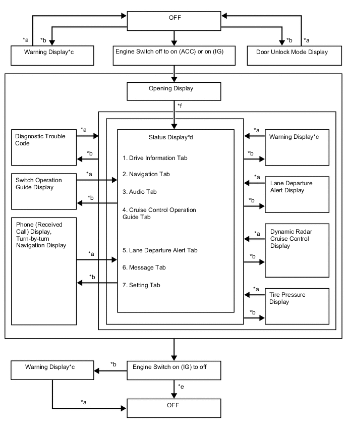
*a Conditions are not met *b Conditions are met *c If there are multiple display requests, items will be displayed in sequence *d Item or display is selected by operating the DISP switch *e ODO display is displayed for a certain period of time after the engine switch is turned off *f After engine switch is turned on (IG) -
Multi-information display (for TFT Meter Type) flow chart
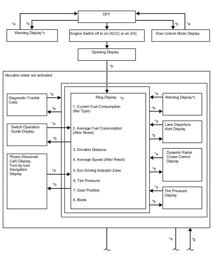
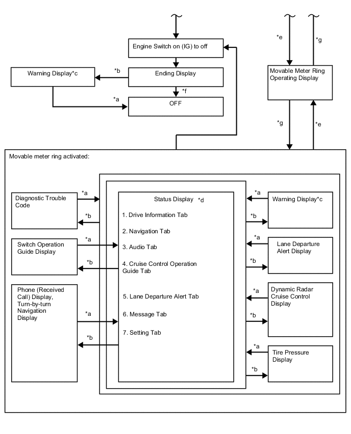
*a Conditions are not met *b Conditions are met *c If there are multiple display requests, items will be displayed in sequence *d Item or display is selected by operating the DISP switch *e Operating the TOP switch *f ODO display is displayed for a certain period of time after the engine switch is turned off *g Movable meter ring activated *h After engine switch is turned on (IG)
-
-
DESCRIPTION OF WARNING DISPLAYS
Priority System name/(Vehicle Function) Master Warning Light
○: Comes on
●: Blinks
Buzzer (*1) Display Level 1 Variable gear ratio steering system - - VGRS Test Mode Caution Dynamic rear steering system - - DRS Test Mode Caution Lane departure alert system - - Adjusting LDA Camera Caution Dynamic radar cruise control system - - Adjusting Front Radar Beam Caution Pre-crash safety system - - BRAKE! Warning Entry and start system ● * Holding in Engine Switch Will Cause an Emergency Engine Stop. Warning ● * To Restart Car, Shift Lever to "N" and Press Engine Switch. Caution (Vehicle roll-away warning) ● * The Engine Has Stopped. Please Put Shift Lever into "P". Caution ● * The Engine Has Stopped. Please Stop Your Car in a Safe Place. Caution 2 Dynamic radar cruise control system or Lane departure alert system - - Dynamic radar cruise control or Lane departure alert warning reminder indicator - Vehicle stability control system ○ ○ Brake Malfunction Warning Brake override system ● ○ The Accelerator is Stuck. Please Depress Brake Pedal to Stop Car. Caution 3 (Each door warning (vehicle being driven)) ● * Each door ajar (vehicle being driven) Caution (Each door warning (vehicle stopped)) - - Each door ajar (vehicle stopped) Caution LEXUS parking assist-sensor system - - Clearance sonar detection (image display) Caution ○ - Check Park Sonar System Caution ○ - Clean Park Sonar Caution 4 Entry and start system - * Auto Power OFF to Conserve Battery Caution 5 Entry and start system ● * Shift to P position when parked Caution Power steering system ○ * EPS Failure. Steering Wheel Harder to Turn. Caution ○ * Voltage Abnormality. Steering Wheel Harder to Turn. Caution ○ * Check Power Steering System Caution (Parking brake) ● * Release Parking Brake Caution Entry and start system ● * Key not detected Caution 6 Automatic transmission system ○ * 1st Gear not available due to slippery road surface Caution (Speedometer) ● * Speed Limit Exceeded Caution 7 Airbag system ○ ○ Check SRS Airbag System Caution Vehicle stability control system - ○ Check ABS Caution SFI system ○ * Engine Coolant High Temperature Caution Dynamic radar cruise control system ○ ○ Clean Radar Sensor Caution ○ ○ Cruise Control not available Caution Lane departure alert system ○ ○ LDA not available Caution Entry and start system ● * Check Access System with Elec. Key Caution Blind spot monitor system ○ ○ BSM not available Caution Dynamic radar cruise control system ○ ○ Check Cruise Control System Caution Lane departure alert system ○ ○ Check LDA System Caution Pre-crash safety system ○ ○ Check PCS System Caution Blind spot monitor system ○ ○ Check BSM System Caution (Engine oil pressure switch assembly) ○ * Engine Oil Pressure Low Caution Automatic transmission system ○ ○ Transmission Fluid High Temperature Caution Variable gear ratio steering system ○ ○ Check VGRS System Caution Dynamic rear steering system ○ ○ Check DRS System Caution Airbag system ○ ○ POP UP HOOD Activated. Caution Airbag system ○ ○ POP UP HOOD Failure. Caution Lane departure alert system - - LDA System is Unavailable Below 50 km/h. Advisory - - LDA System is Unavailable at this Speed. Advisory 8 Dynamic radar cruise control system or Lane departure alert system - - Dynamic radar cruise control or Lane departure alert indicator - Power steering system ○ * Engine Stopped, Steering Wheel Harder to Turn. Caution Entry and start system ● * Turn Power OFF Caution ● ○ Key detected in vehicle Caution Lighting system ● * Turn Light Off Caution Sliding roof system ● ○ Moon Roof opened Caution Power window control system ● ○ Window opened Caution Power window control system or Sliding roof system ● ○ Window / Moon Roof opened Caution Entry and start system ● * Depress brake pedal, touch engine switch with key Caution - -/* Depress brake pedal and push engine switch to start Caution Brake override system ● ○ The Accelerator is Stuck. Please Check the Accelerator. Caution 9 Steering lock system ● * Steering Lock active Caution Brake override system ○ ○ Brake Override System Failure. Caution 10 Entry and start system ○ * Key Battery Low Caution (Engine oil level sensor) ○ ○ Engine Oil Level Low Caution Lighting system, Automatic headlight beam level control system or Automatic high beam system ○ ○ Check Headlight System Caution Brake override system ● - Both Accelerator and Brake Pedals Are Depressed. Advisory Tire pressure warning system - - Tire pressure indicator Advisory 11 Variable gear ratio steering system ○ - Check VGRS System Caution Dynamic rear steering system ○ - Check DRS System Caution (Level warning switch assembly) - - Washer Fluid Low Advisory (Fuel sender gauge assembly)
(No. 2 fuel sender gauge assembly)
- - Fuel Low Advisory Vehicle stability control system - - TRC OFF Caution SFI system ○ - Injector Maintenance required soon Advisory ○ - Injector Maintenance required Advisory Automatic high beam system - - Turn on the high beam to activate AHB System Advisory Entry and start system - - Depress brake pedal and push engine switch to start Caution Pre-crash safety system - - VSC System Switched Off. Pre-Crash Brake System Disengaged. Advisory - - PCS temporarily not available Advisory Air conditioning system - - Operation of Electrical Items Restricted. Advisory Theft deterrent system - - Theft Sensor OFF Caution - - Theft Sensor ON Caution
-
*: An exclusive buzzer sounds depending on condition
-
*1: Buzzers that are linked with the master warning light
-