NETWORK GATEWAY ECU INSTALLATION
CAUTION / NOTICE / HINT
Tech Tips
-
Use the same procedure for the RH side and LH side.
-
The following procedure is for the LH side.
PROCEDURE
-
INSTALL CENTRAL GATEWAY ECU (NETWORK GATEWAY ECU)
-
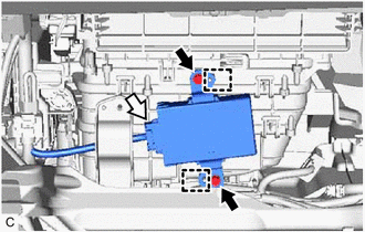
Align the holes of the central gateway ECU (network gateway ECU) with the pins of the blower assembly and install the central gateway ECU (network gateway ECU) with the 2 bolts.
- Torque:
- 5.5 N*m { 56 kgf*cm, 49 in.*lbf }
-
Connect the central gateway ECU (network gateway ECU) connector.
-
-
INSTALL GLOVE COMPARTMENT DOOR ASSEMBLY
-
INSTALL LOWER NO. 2 INSTRUMENT PANEL AIRBAG ASSEMBLY
-
INSTALL FRONT NO. 2 CONSOLE BOX INSERT (for LHD)
-
INSTALL FRONT NO. 1 CONSOLE BOX INSERT (for RHD)
-
INSTALL INSTRUMENT PANEL FINISH PANEL END RH (for LHD)
-
INSTALL INSTRUMENT PANEL FINISH PANEL END LH (for RHD)
-
CONNECT CABLE TO NEGATIVE BATTERY TERMINAL
Note
When disconnecting the cable, some systems need to be initialized after the cable is reconnected.
-
PERFORM DIAGNOSTIC SYSTEM CHECK
-
INSPECT SRS WARNING LIGHT