CAN COMMUNICATION SYSTEM Open in Bus 4 Main Bus Line
DESCRIPTION
There may be an open circuit in one of the CAN main bus lines and/or a central gateway ECU (network gateway ECU) branch line when the resistance between terminals 22 (CA2H) and 7 (CA2L) of the central gateway ECU (network gateway ECU) is 70 Ω or higher.
| Symptom | Trouble Area |
|---|---|
| Resistance between terminals 22 (CA2H) and 7 (CA2L) of the central gateway ECU (network gateway ECU) is 70 Ω or higher. |
|
This malfunction is not related to the lines of a CAN branch except the central gateway ECU (network gateway ECU) branch lines or to ECUs or sensors connected to a CAN branch.
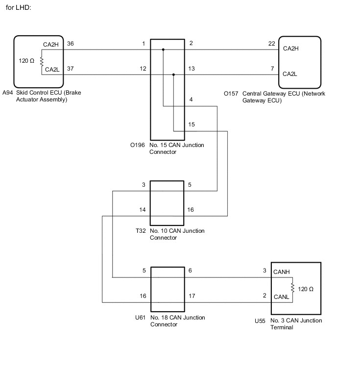
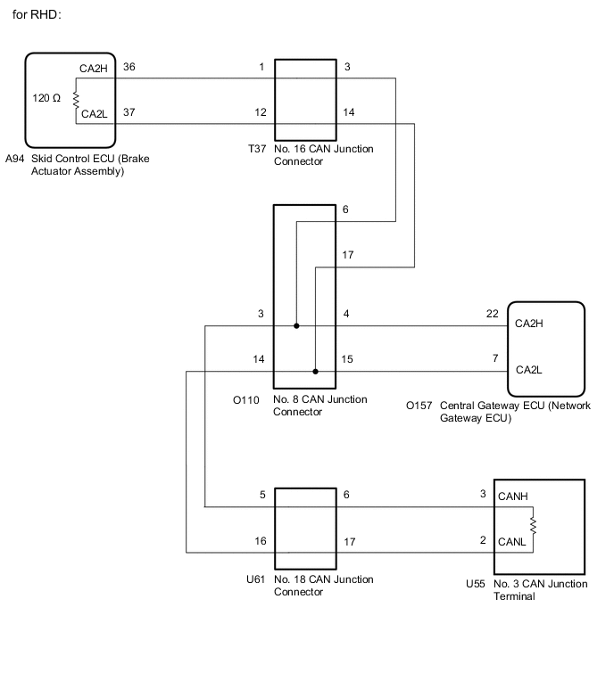
WIRING DIAGRAM
CAUTION / NOTICE / HINT
CAUTION:
When performing the confirmation driving pattern, obey all speed limits and traffic laws.
Note
-
Because the order of diagnosis is important to allow correct diagnosis, make sure to begin troubleshooting using How to Proceed with Troubleshooting when CAN communication system related DTCs are output.
-
Before measuring the resistance of the CAN bus, turn the engine switch off and leave the vehicle for 1 minute or more without operating the key or any switches, or opening or closing the doors. After that, disconnect the cable from the negative (-) battery terminal and leave the vehicle for 1 minute or more before measuring the resistance.
-
After turning the engine switch off, waiting time may be required before disconnecting the cable from the negative (-) battery terminal. Therefore, make sure to read the disconnecting the cable from the negative (-) battery terminal notices before proceeding with work.
-
After performing repairs, perform the DTC check procedure and confirm that the DTCs are not output again.
DTC check procedure: Turn the engine switch on (IG) and wait for 1 minute or more. Then operate the suspected malfunctioning system and drive the vehicle at 60 km/h (37 mph) or more for 5 minutes or more.
-
After the repair, perform the CAN bus check and check that all the ECUs and sensors connected to the CAN communication system are displayed as normal.
Tech Tips
-
Before disconnecting related connectors for inspection, push in on each connector body to check that the connector is not loose or disconnected.
-
When a connector is disconnected, check that the terminals and connector body are not cracked, deformed or corroded.
PROCEDURE
-
CHECK FOR OPEN IN CAN BUS LINES (CENTRAL GATEWAY ECU (NETWORK GATEWAY ECU) BRANCH LINE)
-
Disconnect the cable from the negative (-) battery terminal.
-
Disconnect the O157 central gateway ECU (network gateway ECU) connector.
-
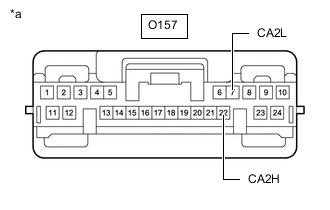
*a Front view of wire harness connector
(to Central Gateway ECU (Network Gateway ECU))
Measure the resistance according to the value(s) in the table below.
Standard Resistance Tester Connection Condition Specified Condition O157-22 (CA2H) - O157-7 (CA2L) Cable disconnected from negative (-) battery terminal 108 to 132 Ω Note
When the measured value is 133 Ω or higher and a CAN communication system DTC is output, there may be a fault besides disconnection of the central gateway ECU (network gateway ECU) branch line. For that reason, troubleshooting should be performed again from How to Proceed with Troubleshooting after repairing the trouble area.
Result Result OK NG
NG 
REPAIR OR REPLACE CAN BRANCH LINES CONNECTED TO CENTRAL GATEWAY ECU (NETWORK GATEWAY ECU)
OK 
-
-
CHECK FOR OPEN IN CAN MAIN BUS LINES (SKID CONTROL ECU (BRAKE ACTUATOR ASSEMBLY))
-
Disconnect the A94 skid control ECU (brake actuator assembly) connector.
-
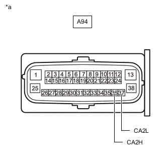
*a Front view of wire harness connector
(to Skid Control ECU (Brake Actuator Assembly))
Measure the resistance according to the value(s) in the table below.
Standard Resistance Tester Connection Condition Specified Condition A94-36 (CA2H) - A94-37 (CA2L) Cable disconnected from negative (-) battery terminal 108 to 132 Ω Result Result Proceed to OK (for LHD) A OK (for RHD) B NG C
A
REPLACE SKID CONTROL ECU (BRAKE ACTUATOR ASSEMBLY) Click here
B
REPLACE SKID CONTROL ECU (BRAKE ACTUATOR ASSEMBLY) Click here
C
-
-
CHECK FOR OPEN IN CAN MAIN BUS LINES (NO. 3 CAN JUNCTION TERMINAL)
-
Reconnect the A94 skid control ECU (brake actuator assembly) connector.
-
Disconnect the U55 No. 3 CAN junction terminal connector.
-
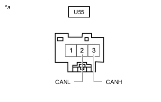
*a Front view of wire harness connector
(to No. 3 CAN Junction Terminal)
Measure the resistance according to the value(s) in the table below.
Standard Resistance Tester Connection Condition Specified Condition U55-3 (CANH) - U55-2 (CANL) Cable disconnected from negative (-) battery terminal 108 to 132 Ω Result Result Proceed to OK A NG (for LHD) B NG (for RHD) C
A
REPLACE NO. 3 CAN JUNCTION TERMINAL
C 
CHECK FOR OPEN IN CAN MAIN BUS LINES (NO. 16 CAN JUNCTION CONNECTOR) Click here
B
-
-
CHECK FOR OPEN IN CAN MAIN BUS LINES (NO. 15 CAN JUNCTION CONNECTOR)
-
Reconnect the U55 No. 3 CAN junction terminal connector.
-
Disconnect the O196 No. 15 CAN junction connector.
-
Measure the resistance according to the value(s) in the table below.
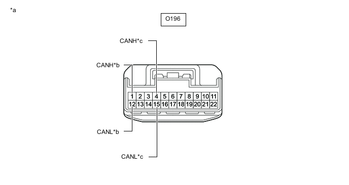
*a Front view of wire harness connector
(to No. 15 CAN Junction Connector)
*b to Skid Control ECU (Brake Actuator Assembly) *c to No. 10 CAN Junction Connector - - Standard Resistance Tester Connection Condition Specified Condition Connected to O196-1 (CANH) - O196-12 (CANL) Cable disconnected from negative (-) battery terminal 108 to 132 Ω Skid control ECU (brake actuator assembly) O196-4 (CANH) - O196-15 (CANL) Cable disconnected from negative (-) battery terminal 108 to 132 Ω No. 10 CAN junction connector Result Result Proceed to OK A NG (Line to skid control ECU (brake actuator assembly)) B NG (Line to No. 10 CAN junction connector) C
A
REPLACE NO. 15 CAN JUNCTION CONNECTOR
B
REPAIR OR REPLACE CAN MAIN BUS LINES OR CONNECTOR (NO. 15 CAN JUNCTION CONNECTOR - SKID CONTROL ECU (BRAKE ACTUATOR ASSEMBLY))
C
-
-
CHECK FOR OPEN IN CAN MAIN BUS LINES (NO. 10 CAN JUNCTION CONNECTOR)
-
Reconnect the O196 No. 15 CAN junction connector.
-
Disconnect the T32 No. 10 CAN junction connector.
-
Measure the resistance according to the value(s) in the table below.
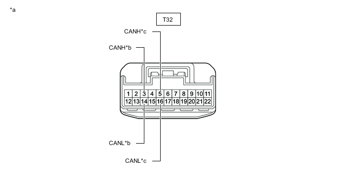
*a Front view of wire harness connector
(to No. 10 CAN Junction Connector)
*b to No. 18 CAN Junction Connector *c to No. 15 CAN Junction Connector - - Standard Resistance Tester Connection Condition Specified Condition Connected to T32-3 (CANH) - T32-14 (CANL) Cable disconnected from negative (-) battery terminal 108 to 132 Ω No. 18 CAN junction connector T32-5 (CANH) - T32-16 (CANL) Cable disconnected from negative (-) battery terminal 108 to 132 Ω No. 15 CAN junction connector Result Result Proceed to OK A NG (Line to No. 15 CAN junction connector) B NG (Line to No. 18 CAN junction connector) C
A
REPLACE NO. 10 CAN JUNCTION CONNECTOR
B
REPAIR OR REPLACE CAN MAIN BUS LINES OR CONNECTOR (NO. 10 CAN JUNCTION CONNECTOR - NO. 15 CAN JUNCTION CONNECTOR)
C
-
-
CHECK FOR OPEN IN CAN MAIN BUS LINES (NO. 18 CAN JUNCTION CONNECTOR)
-
Reconnect the T32 No. 10 CAN junction connector.
-
Disconnect the U61 No. 18 CAN junction connector.
-
Measure the resistance according to the value(s) in the table below.
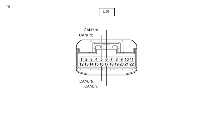
*a Front view of wire harness connector
(to No. 18 CAN Junction Connector)
*b to No. 10 CAN Junction Connector *c to No. 3 CAN Junction Terminal - - Standard Resistance Tester Connection Condition Specified Condition Connected to U61-5 (CANH) - U61-16 (CANL) Cable disconnected from negative (-) battery terminal 108 to 132 Ω No. 10 CAN junction connector U61-6 (CANH) - U61-17 (CANL) Cable disconnected from negative (-) battery terminal 108 to 132 Ω No. 3 CAN junction terminal Result Result Proceed to OK A NG (Line to No. 10 CAN junction connector) B NG (Line to No. 3 CAN junction terminal) C
A
REPLACE NO. 18 CAN JUNCTION CONNECTOR
B
REPAIR OR REPLACE CAN MAIN BUS LINES OR CONNECTOR (NO. 18 CAN JUNCTION CONNECTOR - NO. 10 CAN JUNCTION CONNECTOR)
C
REPAIR OR REPLACE CAN MAIN BUS LINES OR CONNECTOR (NO. 18 CAN JUNCTION CONNECTOR - NO. 3 CAN JUNCTION TERMINAL)
-
-
CHECK FOR OPEN IN CAN MAIN BUS LINES (NO. 16 CAN JUNCTION CONNECTOR)
-
Reconnect the U55 No. 3 CAN junction terminal connector.
-
Disconnect the T37 No. 16 CAN junction connector.
-
Measure the resistance according to the value(s) in the table below.
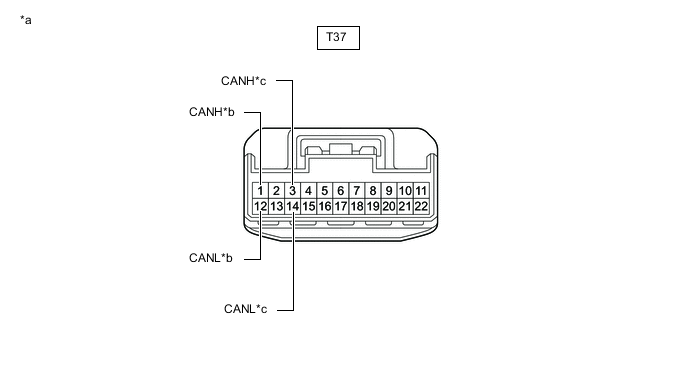
*a Front view of wire harness connector
(to No. 16 CAN Junction Connector)
*b to Skid Control ECU (Brake Actuator Assembly) *c to No. 8 CAN Junction Connector - - Standard Resistance Tester Connection Condition Specified Condition Connected to T37-1 (CANH) - T37-12 (CANL) Cable disconnected from negative (-) battery terminal 108 to 132 Ω Skid control ECU (brake actuator assembly) T37-3 (CANH) - T37-14 (CANL) Cable disconnected from negative (-) battery terminal 108 to 132 Ω No. 8 CAN junction connector Result Result Proceed to OK A NG (Line to skid control ECU (brake actuator assembly)) B NG (Line to No. 8 CAN junction connector) C
A
REPLACE NO. 16 CAN JUNCTION CONNECTOR
B
REPAIR OR REPLACE CAN MAIN BUS LINES OR CONNECTOR (NO. 16 CAN JUNCTION CONNECTOR - SKID CONTROL ECU (BRAKE ACTUATOR ASSEMBLY))
C
-
-
CHECK FOR OPEN IN CAN MAIN BUS LINES (NO. 8 CAN JUNCTION CONNECTOR)
-
Reconnect the T37 No. 16 CAN junction connector.
-
Disconnect the O110 No. 8 CAN junction connector.
-
Measure the resistance according to the value(s) in the table below.
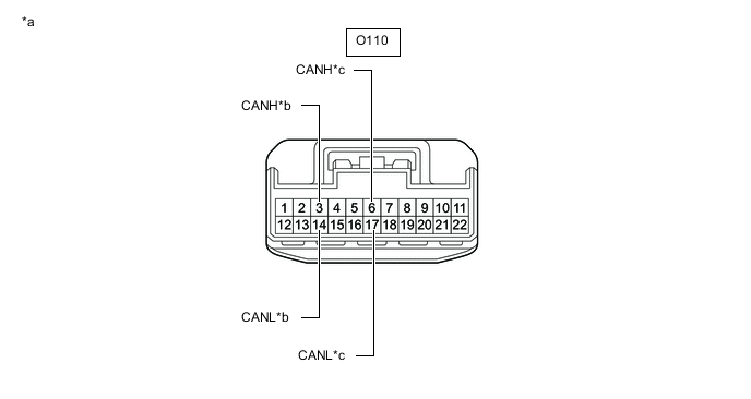
*a Front view of wire harness connector
(to No. 8 CAN Junction Connector)
*b to No. 18 CAN Junction Connector *c to No. 16 CAN Junction Connector - - Standard Resistance Tester Connection Condition Specified Condition Connected to O110-3 (CANH) - O110-14 (CANL) Cable disconnected from negative (-) battery terminal 108 to 132 Ω No. 18 CAN junction connector O110-6 (CANH) - O110-17 (CANL) Cable disconnected from negative (-) battery terminal 108 to 132 Ω No. 16 CAN junction connector Result Result Proceed to OK A NG (Line to No. 16 CAN junction connector) B NG (Line to No. 18 CAN junction connector) C
A
REPLACE NO. 8 CAN JUNCTION CONNECTOR
B
REPAIR OR REPLACE CAN MAIN BUS LINES OR CONNECTOR (NO. 8 CAN JUNCTION CONNECTOR - NO. 16 CAN JUNCTION CONNECTOR)
C
-
-
CHECK FOR OPEN IN CAN MAIN BUS LINES (NO. 18 CAN JUNCTION CONNECTOR)
-
Reconnect the O110 No. 8 CAN junction connector.
-
Disconnect the U61 No. 18 CAN junction connector.
-
Measure the resistance according to the value(s) in the table below.

*a Front view of wire harness connector
(to No. 18 CAN Junction Connector)
*b to No. 8 CAN Junction Connector *c to No. 3 CAN Junction Terminal - - Standard Resistance Tester Connection Condition Specified Condition Connected to U61-5 (CANH) - U61-16 (CANL) Cable disconnected from negative (-) battery terminal 108 to 132 Ω No. 8 CAN junction connector U61-6 (CANH) - U61-17 (CANL) Cable disconnected from negative (-) battery terminal 108 to 132 Ω No. 3 CAN junction terminal Result Result Proceed to OK A NG (Line to No. 8 CAN junction connector) B NG (Line to No. 3 CAN junction terminal) C
A
REPLACE NO. 18 CAN JUNCTION CONNECTOR
B
REPAIR OR REPLACE CAN MAIN BUS LINES OR CONNECTOR (NO. 18 CAN JUNCTION CONNECTOR - NO. 8 CAN JUNCTION CONNECTOR)
C
REPAIR OR REPLACE CAN MAIN BUS LINES OR CONNECTOR (NO. 18 CAN JUNCTION CONNECTOR - NO. 3 CAN JUNCTION TERMINAL)
-