CAN COMMUNICATION SYSTEM, Diagnostic DTC:U1002
| DTC Code | DTC Name |
|---|---|
| U1002 | Lost Communication with Gateway Module (Network Gateway ECU) |
DESCRIPTION
-
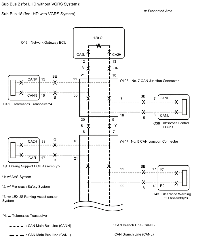
The network gateway ECU will store this DTC when no signals can be received from the ECUs that have been memorized as those that are connected to sub bus 2 (w/o VGRS System) or sub bus 18 (w/ VGRS System).
-
When the network gateway ECU receives a response signal from the ECUs connected to sub bus 2 (w/o VGRS System) or sub bus 18 (w/ VGRS System), the network gateway ECU recognizes and memorizes that the ECU is connected to sub bus 2 (w/o VGRS System) or sub bus 18 (w/ VGRS System). Based on this memorized data, the network gateway ECU monitors for malfunctions in the ECUs connected to sub bus 2 (w/o VGRS System) or sub bus 18 (w/ VGRS System) when communicating with those ECUs. If the network gateway ECU cannot receive response signals from the ECUs that have been memorized as those connected to sub bus 2 (w/o VGRS System) or sub bus 18 (w/ VGRS System), the network gateway ECU determines that a malfunction exists.
| DTC No. | Detection Item | DTC Detection Condition | Trouble Area | Note |
|---|---|---|---|---|
| U1002 | Lost Communication with Gateway Module (Network Gateway ECU) | The network gateway ECU cannot receive signals from all ECUs that have been memorized as those connected to sub bus 2 (w/o VGRS System) or sub bus 18 (w/ VGRS System). |
|
Tech Tips The network gateway ECU stores DTCs when it detects a communication stop or network communication error for ECUs connected to sub bus 2 (w/o VGRS System) or sub bus 18 (w/ VGRS System). |
Tech Tips
This diagnostic procedure is for when DTC U1002 is output by the network gateway ECU (GTS display: Gateway).
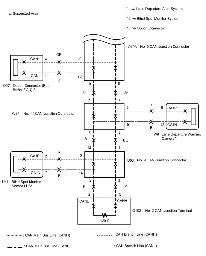
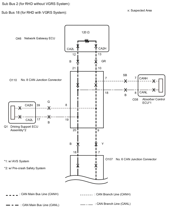
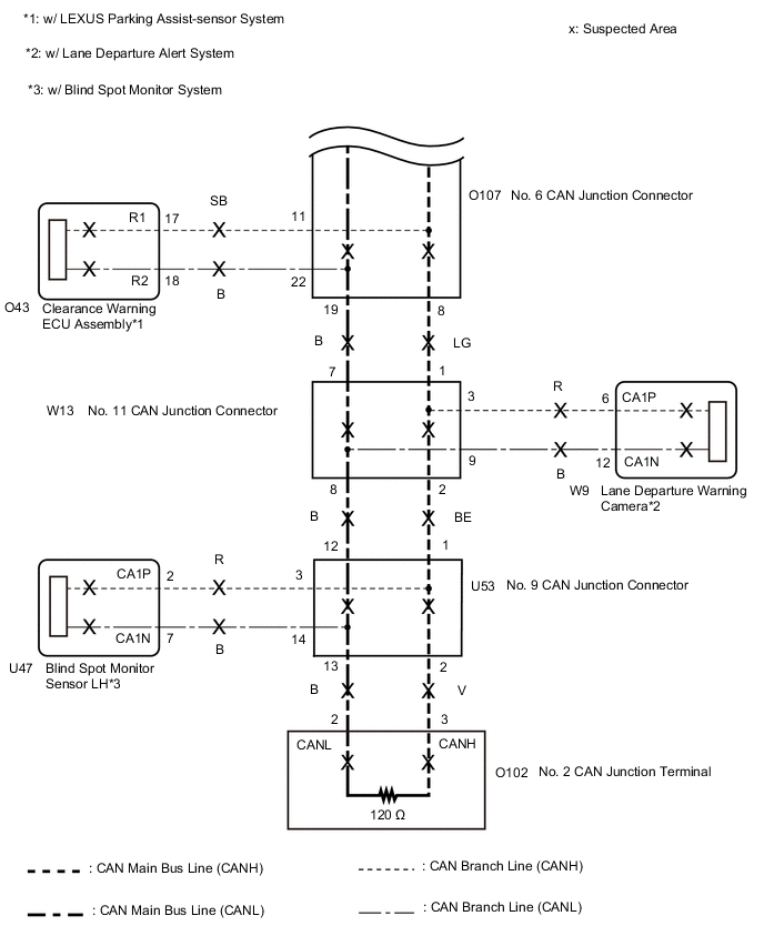
WIRING DIAGRAM
CAUTION / NOTICE / HINT
Note
-
Before measuring the resistance of the CAN bus, turn the engine switch off and leave the vehicle for 1 minute or more without operating the key or any switches, or opening or closing the doors. After that, disconnect the cable from the negative (-) battery terminal and leave the vehicle for 1 minute or more before measuring the resistance.
-
After turning the engine switch off, waiting time may be required before disconnecting the cable from the negative (-) battery terminal. Therefore, make sure to read the disconnecting the cable from the negative (-) battery terminal notices before proceeding with work.
-
Because the order of diagnosis is important to allow correct diagnosis, make sure to begin troubleshooting using How to Proceed with Troubleshooting when CAN communication system related DTCs are output.
-
After performing repairs, perform the DTC check procedure and confirm that the DTCs are not output again.
-
DTC check procedure: Turn the engine switch on (IG), wait at least 52 seconds, turn the blind spot monitor main switch on, turn the cruise control main switch on and then drive the vehicle at a speed of 40 km/h (25 mph) or more for 11.85 seconds or more.
-
After the repair, perform the CAN bus check and check that all the ECUs and sensors connected to the CAN communication system are displayed.
Tech Tips
-
Operating the engine switch, any other switches or a door triggers related ECU and sensor communication on the CAN. This communication will cause the resistance value to change.
-
Even after DTCs are cleared, if a DTC is stored again after driving the vehicle for a while, the malfunction may be occurring due to vibration of the vehicle. In such a case, wiggling the ECUs or wire harness while performing the inspection below may help determine the cause of the malfunction.
PROCEDURE
-
CHECK VEHICLE TYPE
-
Check vehicle type.
Result Result Proceed to for LHD A for RHD B
B 
CHECK SUB BUS Click here
A 
-
-
CHECK SUB BUS
-
Disconnect the cable from the negative (-) battery terminal.
-

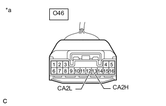
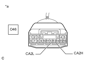
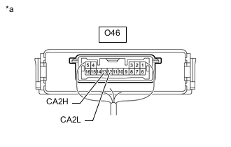
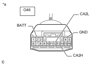
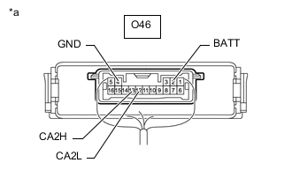
*a Component with harness connected
(Network Gateway ECU)
Measure the resistance according to the value(s) in the table below.
Standard Resistance Tester Connection Condition Specified Condition Result O46-13 (CA2H) - O46-12 (CA2L) Cable disconnected from negative (-) battery terminal 54 to 69 Ω Below 54 Ω: Short circuit between bus lines 70 Ω or higher: Open circuit in main bus lines O46-13 (CA2H) - O46-4 (GND) Cable disconnected from negative (-) battery terminal 200 Ω or higher Below 200 Ω: CANH short to ground O46-12 (CA2L) - O46-4 (GND) Cable disconnected from negative (-) battery terminal 200 Ω or higher Below 200 Ω: CANL short to ground O46-13 (CA2H) - O46-2 (BATT) Cable disconnected from negative (-) battery terminal 6 kΩ or higher Below 6 kΩ: CANH +B short O46-12 (CA2L) - O46-2 (BATT) Cable disconnected from negative (-) battery terminal 6 kΩ or higher Below 6 kΩ: CANL +B short Result Result Proceed to OK A Open circuit in CAN main bus lines B Short circuit between bus lines C
-
Short to ground
-
+B short
D -
B
CHECK FOR OPEN IN SUB BUS MAIN LINES (NETWORK GATEWAY ECU) Click here
C
CHECK FOR SHORT IN SUB BUS LINES (NETWORK GATEWAY ECU) Click here
D
CHECK FOR SHORT IN SUB BUS LINE (NO. 7 CAN JUNCTION CONNECTOR) Click here
A
-
-
CHECK FOR DTC OUTPUT
-
Reconnect the cable to the negative (-) battery terminal.
-
Connect the GTS to the DLC3.
-
Turn the engine switch on (IG).
-
Turn the GTS on.
-
Clear the DTCs.
Body Electrical > Gateway > Clear DTCs -
Turn the engine switch off.
-
Turn the engine switch on (IG).
-
Check for DTCs.
Body Electrical > Gateway > Trouble CodesResult Result Proceed to DTC U1002 is not output from the network gateway ECU (GTS display: Gateway) A DTC U1002 is output from the network gateway ECU (GTS display: Gateway) B
A 
SYMPTOM SIMULATION Click here
B
REPLACE NETWORK GATEWAY ECU Click here
-
-
CHECK FOR OPEN IN SUB BUS MAIN LINES (NETWORK GATEWAY ECU)
-
*a Front view of wire harness connector
(to Network Gateway ECU)
Disconnect the O46 network gateway ECU connector.
-
Measure the resistance according to the value(s) in the table below.
Standard Resistance Tester Connection Condition Specified Condition O46-13 (CA2H) - O46-12 (CA2L) Cable disconnected from negative (-) battery terminal 108 to 132 Ω Result Result OK NG
OK
REPLACE NETWORK GATEWAY ECU Click here
NG
-
-
CHECK FOR OPEN IN SUB BUS MAIN LINES (NO. 2 CAN JUNCTION TERMINAL)
-
Reconnect the O46 network gateway ECU connector.
-
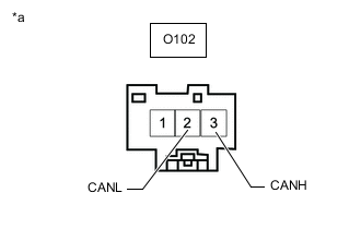
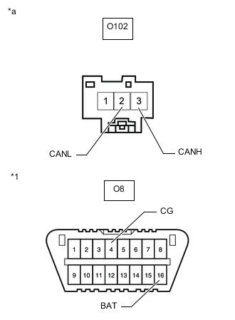
*a Front view of wire harness connector
(to No. 2 CAN Junction Terminal)
Disconnect the O102 No. 2 CAN junction terminal connector.
-
Measure the resistance according to the value(s) in the table below.
Standard Resistance Tester Connection Condition Specified Condition O102-3 (CANH) - O102-2 (CANL) Cable disconnected from negative (-) battery terminal 108 to 132 Ω Result Result OK NG
OK
REPLACE NO. 2 CAN JUNCTION TERMINAL
NG
-
-
CHECK FOR OPEN IN SUB BUS MAIN LINES (NO. 7 CAN JUNCTION CONNECTOR)
-
Reconnect the O102 No. 2 CAN junction terminal connector.
-
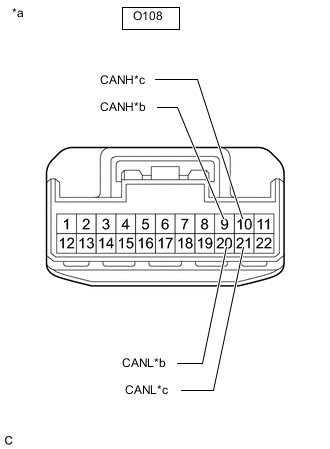
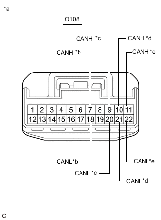
*a Front view of wire harness connector
(to No. 7 CAN Junction Connector)
*b to No. 5 CAN Junction Connector *c to Network Gateway ECU Disconnect the O108 No. 7 CAN junction connector.
-
Measure the resistance according to the value(s) in the table below.
Standard Resistance Tester Connection Condition Specified Condition Connected to O108-9 (CANH) - O108-20 (CANL) Cable disconnected from negative (-) battery terminal 108 to 132 Ω No. 5 CAN junction connector O108-10 (CANH) - O108-21 (CANL) Cable disconnected from negative (-) battery terminal 108 to 132 Ω Network gateway ECU Result Result Proceed to OK A NG (Network gateway ECU main lines) B NG (No. 5 CAN junction connector main lines) C
A
REPLACE NO. 7 CAN JUNCTION CONNECTOR
B
REPAIR OR REPLACE CAN MAIN BUS LINES OR CONNECTOR (NETWORK GATEWAY ECU - NO. 7 CAN JUNCTION CONNECTOR)
C
-
-
CHECK FOR OPEN IN SUB BUS MAIN LINES (NO. 5 CAN JUNCTION CONNECTOR)
-
Reconnect the O108 No. 7 CAN junction connector.
-

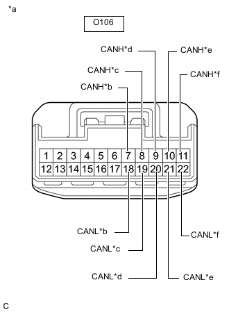
*a Front view of wire harness connector
(to No. 5 CAN Junction Connector)
*b to No. 7 CAN Junction Connector *c to No. 11 CAN Junction Connector Disconnect the O106 No. 5 CAN junction connector.
-
Measure the resistance according to the value(s) in the table below.
Standard Resistance Tester Connection Condition Specified Condition Connected to O106-7 (CANH) - O106-18 (CANL) Cable disconnected from negative (-) battery terminal 108 to 132 Ω No. 7 CAN junction connector O106-8 (CANH) - O106-19 (CANL) Cable disconnected from negative (-) battery terminal 108 to 132 Ω No. 11 CAN junction connector Result Result Proceed to OK A NG (No. 7 CAN junction connector main lines) B NG (No. 11 CAN junction connector main lines) C
A
REPLACE NO. 5 CAN JUNCTION CONNECTOR
B
REPAIR OR REPLACE CAN MAIN BUS LINES OR CONNECTOR (NO. 5 CAN JUNCTION CONNECTOR - NO. 7 CAN JUNCTION CONNECTOR)
C
-
-
CHECK FOR OPEN IN SUB BUS MAIN LINES (NO. 11 CAN JUNCTION CONNECTOR)
-
Reconnect the O106 No. 5 CAN junction connector.
-
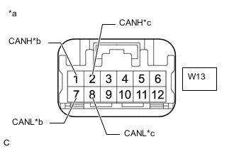
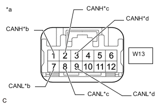
*a Front view of wire harness connector
(to No. 11 CAN Junction Connector)
*b to No. 5 CAN Junction Connector *c to No. 9 CAN Junction Connector Disconnect the W13 No. 11 CAN junction connector.
-
Measure the resistance according to the value(s) in the table below.
Standard Resistance Tester Connection Condition Specified Condition Connected to W13-1 (CANH) - W13-7 (CANL) Cable disconnected from negative (-) battery terminal 108 to 132 Ω No. 5 CAN junction connector W13-2 (CANH) - W13-8 (CANL) Cable disconnected from negative (-) battery terminal 108 to 132 Ω No. 9 CAN junction connector Result Result Proceed to OK A NG (No. 5 CAN junction connector main lines) B NG (No. 9 CAN junction connector main lines) C
A
REPLACE NO. 11 CAN JUNCTION CONNECTOR
B
REPAIR OR REPLACE CAN MAIN BUS LINES OR CONNECTOR (NO. 5 CAN JUNCTION CONNECTOR - NO. 11 CAN JUNCTION CONNECTOR)
C
-
-
CHECK FOR OPEN IN SUB BUS MAIN LINES (NO. 9 CAN JUNCTION CONNECTOR)
-
Reconnect the W13 No. 11 CAN junction connector.
-
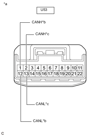
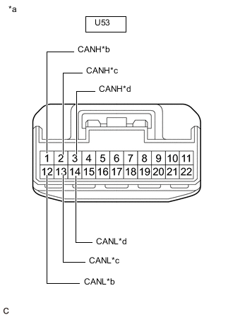
*a Front view of wire harness connector
(to No. 9 CAN Junction Connector)
*b to No. 11 CAN Junction Connector *c to No. 2 CAN Junction Terminal Disconnect the U53 No. 9 CAN junction connector.
-
Measure the resistance according to the value(s) in the table below.
Standard Resistance Tester Connection Condition Specified Condition Connected to U53-1 (CANH) - U53-12 (CANL) Cable disconnected from negative (-) battery terminal 108 to 132 Ω No. 11 CAN junction connector U53-2 (CANH) - U53-13 (CANL) Cable disconnected from negative (-) battery terminal 108 to 132 Ω No. 2 CAN junction terminal Result Result Proceed to OK A NG (No. 11 CAN junction connector main lines) B NG (No. 2 CAN junction terminal main lines) C
A
REPLACE NO. 9 CAN JUNCTION CONNECTOR
B
REPAIR OR REPLACE CAN MAIN BUS LINES OR CONNECTOR (NO. 9 CAN JUNCTION CONNECTOR - NO. 11 CAN JUNCTION CONNECTOR)
C
REPAIR OR REPLACE CAN MAIN BUS LINES OR CONNECTOR (NO. 9 CAN JUNCTION CONNECTOR - NO. 2 CAN JUNCTION TERMINAL)
-
-
CHECK FOR SHORT IN SUB BUS LINES (NETWORK GATEWAY ECU)
-
*a Front view of wire harness connector
(to Network Gateway ECU)
Disconnect the O46 network gateway ECU connector.
-
Measure the resistance according to the value(s) in the table below.
Standard Resistance Tester Connection Condition Specified Condition O46-13 (CA2H) - O46-12 (CA2L) Cable disconnected from negative (-) battery terminal 108 to 132 Ω Result Result OK NG
OK
REPLACE NETWORK GATEWAY ECU Click here
NG
-
-
CHECK FOR SHORT IN SUB BUS LINES (NO. 2 CAN JUNCTION TERMINAL)
-
Reconnect the O46 network gateway ECU connector.
-

*a Front view of wire harness connector
(to No. 2 CAN Junction Terminal)
Disconnect the O102 No. 2 CAN junction terminal connector.
-
Measure the resistance according to the value(s) in the table below.
Standard Resistance Tester Connection Condition Specified Condition O102-3 (CANH) - O102-2 (CANL) Cable disconnected from negative (-) battery terminal 108 to 132 Ω Result Result OK NG
OK
REPLACE NO. 2 CAN JUNCTION TERMINAL
NG
-
-
CHECK FOR SHORT IN SUB BUS LINES (NO. 7 CAN JUNCTION CONNECTOR)
-
Reconnect the O102 No. 2 CAN junction terminal connector.
-
*a Front view of wire harness connector
(to No. 7 CAN Junction Connector)
*b to Absorber Control ECU
(w/ AVS System)
*c to No. 5 CAN Junction Connector *d to Network Gateway ECU *e to Telematcs Transceiver
(w/ Telematics Transceiver)
Disconnect the O108 No. 7 CAN junction connector.
-
Measure the resistance according to the value(s) in the table below.
Standard Resistance Tester Connection Condition Specified Condition Connected to O108-7 (CANH) - O108-18 (CANL) Cable disconnected from negative (-) battery terminal 200 Ω or higher Absorber control ECU*1 O108-9 (CANH) - O108-20 (CANL) Cable disconnected from negative (-) battery terminal 108 to 132 Ω No. 5 CAN junction connector O108-10 (CANH) - O108-21 (CANL) Cable disconnected from negative (-) battery terminal 108 to 132 Ω Network gateway ECU O108-11 (CANH) - O108-22 (CANL) Cable disconnected from negative (-) battery terminal 200 Ω or higher Telematics transceiver*2
-
*1: w/ AVS System
-
*2: w/ Telematics Transceiver
Result Result Proceed to OK A NG (Network gateway ECU main lines) B NG (ECU or sensor branch lines) C NG (No. 5 CAN junction connector main lines) D -
A
REPLACE NO. 7 CAN JUNCTION CONNECTOR
B
REPAIR OR REPLACE CAN MAIN BUS LINES OR CONNECTOR (NETWORK GATEWAY ECU - NO. 7 CAN JUNCTION CONNECTOR)
C
GO TO STEP 16 Click here
D
-
-
CHECK FOR SHORT IN SUB BUS LINES (NO. 5 CAN JUNCTION CONNECTOR)
-
Reconnect the O108 No. 7 CAN junction connector.
-
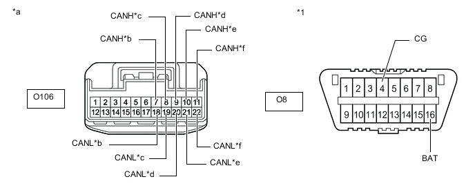
*a Front view of wire harness connector
(to No. 5 CAN Junction Connector)
*b to No. 7 CAN Junction Connector *c to No. 11 CAN Junction Connector *d to Option Connector (Bus Buffer ECU)
(w/ Option Connector)
*e to Driving Support ECU Assembly
(w/ Pre-crash Safety System)
*f to Clearance Warning ECU Assembly
(w/ LEXUS Parking Assist-sensor System)
Disconnect the O106 No. 5 CAN junction connector.
-
Measure the resistance according to the value(s) in the table below.
Standard Resistance Tester Connection Condition Specified Condition Connected to O106-7 (CANH) - O106-18 (CANL) Cable disconnected from negative (-) battery terminal 108 to 132 Ω No. 7 CAN junction connector O106-8 (CANH) - O106-19 (CANL) Cable disconnected from negative (-) battery terminal 108 to 132 Ω No. 11 CAN junction connector O106-9 (CANH) - O106-20 (CANL) Cable disconnected from negative (-) battery terminal 1 MΩ or higher Option connector (bus buffer ECU)*1 O106-10 (CANH) - O106-21 (CANL) Cable disconnected from negative (-) battery terminal 200 Ω or higher Driving support ECU assembly*2 O106-11 (CANH) - O106-22 (CANL) Cable disconnected from negative (-) battery terminal 200 Ω or higher Clearance warning ECU assembly*3
-
*1: w/ Option Connector
-
*2: w/ Pre-crash Safety System
-
*3: w/ LEXUS Parking Assist-sensor System
Result Result Proceed to OK A NG (No. 7 CAN junction connector main lines) B NG (ECU or sensor branch lines) C NG (No. 11 CAN junction connector main lines) D -
A
REPLACE NO. 5 CAN JUNCTION CONNECTOR
B
REPAIR OR REPLACE CAN MAIN BUS LINES OR CONNECTOR (NO. 5 CAN JUNCTION CONNECTOR - NO. 7 CAN JUNCTION CONNECTOR)
C
GO TO STEP 16 Click here
D
-
-
CHECK FOR SHORT IN SUB BUS LINES (NO. 11 CAN JUNCTION CONNECTOR)
-
Reconnect the O106 No. 5 CAN junction connector.
-
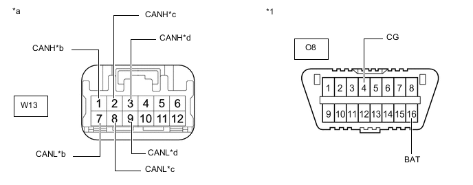
*a Front view of wire harness connector
(to No. 11 CAN Junction Connector)
*b to No. 5 CAN Junction Connector *c to No. 9 CAN Junction Connector *d to Lane Departure Warning Camera
(w/ Lane Departure Alert System)
Disconnect the W13 No. 11 CAN junction connector.
-
Measure the resistance according to the value(s) in the table below.
Standard Resistance Tester Connection Condition Specified Condition Connected to W13-1 (CANH) - W13-7 (CANL) Cable disconnected from negative (-) battery terminal 108 to 132 Ω No. 5 CAN junction connector W13-2 (CANH) - W13-8 (CANL) Cable disconnected from negative (-) battery terminal 108 to 132 Ω No. 9 CAN junction connector W13-3 (CANH) - W13-9 (CANL) Cable disconnected from negative (-) battery terminal 200 Ω or higher Lane departure warning camera*
-
*: w/ Lane Departure Alert System
Result Result Proceed to OK A NG (No. 5 CAN junction connector main lines) B NG (ECU or sensor branch lines) C NG (No. 9 CAN junction connector main lines) D -
A
REPLACE NO. 11 CAN JUNCTION CONNECTOR
B
REPAIR OR REPLACE CAN MAIN BUS LINES OR CONNECTOR (NO. 5 CAN JUNCTION CONNECTOR - NO. 11 CAN JUNCTION CONNECTOR)
C
GO TO STEP 16 Click here
D
-
-
CHECK FOR SHORT IN SUB BUS LINES (NO. 9 CAN JUNCTION CONNECTOR)
-
Reconnect the W13 No. 11 CAN junction connector.
-
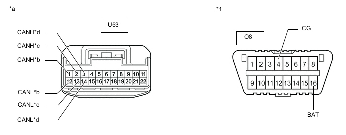
*a Front view of wire harness connector
(to No. 9 CAN Junction Connector)
*b to No. 11 CAN Junction Connector *c to No. 2 CAN Junction Terminal *d to Blind Spot Monitor Sensor LH
(w/ Blind Spot Monitor System)
Disconnect the U53 No. 9 CAN junction connector.
-
Measure the resistance according to the value(s) in the table below.
Standard Resistance Tester Connection Condition Specified Condition Connected to U53-1 (CANH) - U53-12 (CANL) Cable disconnected from negative (-) battery terminal 108 to 132 Ω No. 11 CAN junction connector U53-2 (CANH) - U53-13 (CANL) Cable disconnected from negative (-) battery terminal 108 to 132 Ω No. 2 CAN junction terminal U53-3 (CANH) - U53-14 (CANL) Cable disconnected from negative (-) battery terminal 200 Ω or higher Blind spot monitor sensor LH*
-
*: w/ Blind Spot Monitor System
Result Result Proceed to OK A NG (No. 11 CAN junction connector main lines) B NG (ECU or sensor branch lines) C NG (No. 2 CAN junction terminal main lines) D -
A
REPLACE NO. 9 CAN JUNCTION CONNECTOR
B
REPAIR OR REPLACE CAN MAIN BUS LINES OR CONNECTOR (NO. 9 CAN JUNCTION CONNECTOR - NO. 11 CAN JUNCTION CONNECTOR)
D
REPAIR OR REPLACE CAN MAIN BUS LINES OR CONNECTOR (NO. 9 CAN JUNCTION CONNECTOR - NO. 2 CAN JUNCTION TERMINAL)
C
-
-
CHECK FOR SHORT IN SUB BUS LINES (ECU, SENSOR)
-
Reconnect all wire harness connectors.
-
Disconnect the connector that includes terminals CANH and CANL from the ECU or sensor to which the short circuited branch line is connected.
-
*a Component with harness connected
(Network Gateway ECU)
Measure the resistance according to the value(s) in the table below.
Standard Resistance Tester Connection Condition Specified Condition O46-13 (CA2H) - O46-12 (CA2L) Cable disconnected from negative (-) battery terminal 54 to 69 Ω Tech Tips
If the resistance becomes normal (between 54 and 69 Ω) when the connector is disconnected from the ECU or sensor, there may be a short in the ECU or sensor.
Result Result OK NG
OK
REPLACE CORRESPONDING ECU OR SENSOR
NG
REPAIR OR REPLACE CORRESPONDING ECU OR SENSOR BRANCH LINES OR CONNECTOR
-
-
CHECK FOR SHORT IN SUB BUS LINE (NO. 7 CAN JUNCTION CONNECTOR)
-
Disconnect the O108 No. 7 CAN junction connector.
-
Measure the resistance according to the value(s) in the table below.
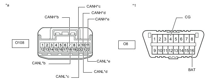
*1 DLC3 - - *a Front view of wire harness connector
(to No. 7 CAN Junction Connector)
*b to Absorber Control ECU
(w/ AVS System)
*c to No. 5 CAN Junction Connector *d to Network Gateway ECU *e to Telematics Transceiver
(w/ Telematics Transceiver)
- - Standard Resistance Tester Connection Condition Specified Condition Result Connected to O108-7 (CANH) - O8-4 (CG) Cable disconnected from negative (-) battery terminal 200 Ω or higher Below 200 Ω: CANH short to ground Absorber control ECU*1 O108-18 (CANL) - O8-4 (CG) Cable disconnected from negative (-) battery terminal 200 Ω or higher Below 200 Ω: CANL short to ground O108-9 (CANH) - O8-4 (CG) Cable disconnected from negative (-) battery terminal 200 Ω or higher Below 200 Ω: CANH short to ground No. 5 CAN junction connector O108-20 (CANL) - O8-4 (CG) Cable disconnected from negative (-) battery terminal 200 Ω or higher Below 200 Ω: CANL short to ground O108-10 (CANH) - O8-4 (CG) Cable disconnected from negative (-) battery terminal 200 Ω or higher Below 200 Ω: CANH short to ground Network gateway ECU O108-21 (CANL) - O8-4 (CG) Cable disconnected from negative (-) battery terminal 200 Ω or higher Below 200 Ω: CANL short to ground O108-11 (CANH) - O8-4 (CG) Cable disconnected from negative (-) battery terminal 200 Ω or higher Below 200 Ω: CANH short to ground Telematics transceiver*2 O108-22 (CANL) - O8-4 (CG) Cable disconnected from negative (-) battery terminal 200 Ω or higher Below 200 Ω: CANL short to ground O108-7 (CANH) - O8-16 (BAT) Cable disconnected from negative (-) battery terminal 6 kΩ or higher Below 6 kΩ: CANH +B short Absorber control ECU*1 O108-18 (CANL) - O8-16 (BAT) Cable disconnected from negative (-) battery terminal 6 kΩ or higher Below 6 kΩ: CANL +B short O108-9 (CANH) - O8-16 (BAT) Cable disconnected from negative (-) battery terminal 6 kΩ or higher Below 6 kΩ: CANH +B short No. 5 CAN junction connector O108-20 (CANL) - O8-16 (BAT) Cable disconnected from negative (-) battery terminal 6 kΩ or higher Below 6 kΩ: CANL +B short O108-10 (CANH) - O8-16 (BAT) Cable disconnected from negative (-) battery terminal 6 kΩ or higher Below 6 kΩ: CANH +B short Network gateway ECU O108-21 (CANL) - O8-16 (BAT) Cable disconnected from negative (-) battery terminal 6 kΩ or higher Below 6 kΩ: CANL +B short O108-11 (CANH) - O8-16 (BAT) Cable disconnected from negative (-) battery terminal 6 kΩ or higher Below 6 kΩ: CANH +B short Telematics Transceiver*2 O108-22 (CANL) - O8-16 (BAT) Cable disconnected from negative (-) battery terminal 6 kΩ or higher Below 6 kΩ: CANL +B short
-
*1: w/ AVS System
-
*2: w/ Telematics Transceiver
Tech Tips
-
It is only necessary to perform the inspection in the above table for the result (short circuit) that was obtained in the Check Sub Bus inspection.
-
Find the necessary inspection from the Result column that matches the result in the Result column from the Check Sub Bus inspection.
Result Result Proceed to OK A NG (Network gateway ECU main line) B NG (ECU or sensor branch line) C NG (No. 5 CAN junction connector main line) D -
A
REPLACE NO. 7 CAN JUNCTION CONNECTOR
C
GO TO STEP 22 Click here
D
CHECK FOR SHORT IN SUB BUS LINE (NO. 5 CAN JUNCTION CONNECTOR) Click here
B
-
-
CHECK FOR SHORT IN SUB BUS LINE (NETWORK GATEWAY ECU)
-
Reconnect the O108 No. 7 CAN junction connector.
-
*a Front view of wire harness connector
(to Network Gateway ECU)
Disconnect the O46 network gateway ECU connector.
-
Measure the resistance according to the value(s) in the table below.
Standard Resistance Tester Connection Condition Specified Condition Result O46-13 (CA2H) - O46-4 (GND) Cable disconnected from negative (-) battery terminal 200 Ω or higher Below 200 Ω: CANH short to ground O46-12 (CA2L) - O46-4 (GND) Cable disconnected from negative (-) battery terminal 200 Ω or higher Below 200 Ω: CANL short to ground O46-13 (CA2H) - O46-2 (BATT) Cable disconnected from negative (-) battery terminal 6 kΩ or higher Below 6 kΩ: CANH +B short O46-12 (CA2L) - O46-2 (BATT) Cable disconnected from negative (-) battery terminal 6 kΩ or higher Below 6 kΩ: CANL +B short Tech Tips
-
It is only necessary to perform the inspection in the above table for the result (short circuit) that was obtained in the Check Sub Bus inspection.
-
Find the necessary inspection from the Result column that matches the result in the Result column from the Check Sub Bus inspection.
Result Result OK NG -
OK
REPLACE NETWORK GATEWAY ECU Click here
NG
REPAIR OR REPLACE CAN MAIN BUS LINE OR CONNECTOR (NETWORK GATEWAY ECU - NO. 7 CAN JUNCTION CONNECTOR)
-
-
CHECK FOR SHORT IN SUB BUS LINE (NO. 5 CAN JUNCTION CONNECTOR)
-
Reconnect the O108 No. 7 CAN junction connector.
-
Disconnect the O106 No. 5 CAN junction connector.
-
Measure the resistance according to the value(s) in the table below.
*1 DLC3 - - *a Front view of wire harness connector
(to No. 5 CAN Junction Connector)
*b to No. 7 CAN Junction Connector *c to No. 11 CAN Junction Connector *d to Option Connector (Bus Buffer ECU)
(w/ Option Connector)
*e to Driving Support ECU Assembly
(w/ Pre-crash Safety System)
*f to Clearance Warning ECU Assembly
(w/ LEXUS Parking Assist-sensor System)
Standard Resistance Tester Connection Condition Specified Condition Result Connected to O106-7 (CANH) - O8-4 (CG) Cable disconnected from negative (-) battery terminal 200 Ω or higher Below 200 Ω: CANH short to ground No. 7 CAN junction connector O106-18 (CANL) - O8-4 (CG) Cable disconnected from negative (-) battery terminal 200 Ω or higher Below 200 Ω: CANL short to ground O106-8 (CANH) - O8-4 (CG) Cable disconnected from negative (-) battery terminal 200 Ω or higher Below 200 Ω: CANH short to ground No. 11 CAN junction connector O106-19 (CANL) - O8-4 (CG) Cable disconnected from negative (-) battery terminal 200 Ω or higher Below 200 Ω: CANL short to ground O106-9 (CANH) - O8-4 (CG) Cable disconnected from negative (-) battery terminal 200 Ω or higher Below 200 Ω: CANH short to ground Option connector (bus buffer ECU)*1 O106-20 (CANL) - O8-4 (CG) Cable disconnected from negative (-) battery terminal 200 Ω or higher Below 200 Ω: CANL short to ground O106-10 (CANH) - O8-4 (CG) Cable disconnected from negative (-) battery terminal 200 Ω or higher Below 200 Ω: CANH short to ground Driving support ECU assembly*2 O106-21 (CANL) - O8-4 (CG) Cable disconnected from negative (-) battery terminal 200 Ω or higher Below 200 Ω: CANL short to ground O106-11 (CANH) - O8-4 (CG) Cable disconnected from negative (-) battery terminal 200 Ω or higher Below 200 Ω: CANH short to ground Clearance warning ECU assembly*3 O106-22 (CANL) - O8-4 (CG) Cable disconnected from negative (-) battery terminal 200 Ω or higher Below 200 Ω: CANL short to ground O106-7 (CANH) - O8-16 (BAT) Cable disconnected from negative (-) battery terminal 6 kΩ or higher Below 6 kΩ: CANH +B short No. 7 CAN junction connector O106-18 (CANL) - O8-16 (BAT) Cable disconnected from negative (-) battery terminal 6 kΩ or higher Below 6 kΩ: CANL +B short O106-8 (CANH) - O8-16 (BAT) Cable disconnected from negative (-) battery terminal 6 kΩ or higher Below 6 kΩ: CANH +B short No. 11 CAN junction connector O106-19 (CANL) - O8-16 (BAT) Cable disconnected from negative (-) battery terminal 6 kΩ or higher Below 6 kΩ: CANL +B short O106-9 (CANH) - O8-16 (BAT) Cable disconnected from negative (-) battery terminal 6 kΩ or higher Below 6 kΩ: CANH +B short Option connector (bus buffer ECU)*1 O106-20 (CANL) - O8-16 (BAT) Cable disconnected from negative (-) battery terminal 6 kΩ or higher Below 6 kΩ: CANL +B short O106-10 (CANH) - O8-16 (BAT) Cable disconnected from negative (-) battery terminal 6 kΩ or higher Below 6 kΩ: CANH +B short Driving support ECU assembly*2 O106-21 (CANL) - O8-16 (BAT) Cable disconnected from negative (-) battery terminal 6 kΩ or higher Below 6 kΩ: CANL +B short O106-11 (CANH) - O8-16 (BAT) Cable disconnected from negative (-) battery terminal 6 kΩ or higher Below 6 kΩ: CANH +B short Clearance warning ECU assembly*3 O106-22 (CANL) - O8-16 (BAT) Cable disconnected from negative (-) battery terminal 6 kΩ or higher Below 6 kΩ: CANL +B short
-
*1: w/ Option Connector
-
*2: w/ Pre-crash Safety System
-
*3: w/ LEXUS Parking Assist-sensor System
Tech Tips
-
It is only necessary to perform the inspection in the above table for the result (short circuit) that was obtained in the Check Sub Bus inspection.
-
Find the necessary inspection from the Result column that matches the result in the Result column from the Check Sub Bus inspection.
Result Result Proceed to OK A NG (ECU or sensor branch line) B NG (No. 7 CAN junction connector main line) C NG (No. 11 CAN junction connector main line) D -
A
REPLACE NO. 5 CAN JUNCTION CONNECTOR
B
GO TO STEP 22 Click here
C
REPAIR OR REPLACE CAN MAIN BUS LINE OR CONNECTOR (NO. 5 CAN JUNCTION CONNECTOR - NO. 7 CAN JUNCTION CONNECTOR)
D
-
-
CHECK FOR SHORT IN SUB BUS LINE (NO. 11 CAN JUNCTION CONNECTOR)
-
Reconnect the O106 No. 5 CAN junction connector.
-
Disconnect the W13 No. 11 CAN junction connector.
-
Measure the resistance according to the value(s) in the table below.
*1 DLC3 - - *a Front view of wire harness connector
(to No. 11 CAN Junction Connector)
*b to No. 5 CAN Junction Connector *c to No. 9 CAN Junction Connector *d to Lane Departure Warning Camera
(w/ Lane Departure Alert System)
Standard Resistance Tester Connection Condition Specified Condition Result Connected to W13-1 (CANH) - O8-4 (CG) Cable disconnected from negative (-) battery terminal 200 Ω or higher Below 200 Ω: CANH short to ground No. 5 CAN junction connector W13-7 (CANL) - O8-4 (CG) Cable disconnected from negative (-) battery terminal 200 Ω or higher Below 200 Ω: CANL short to ground W13-2 (CANH) - O8-4 (CG) Cable disconnected from negative (-) battery terminal 200 Ω or higher Below 200 Ω: CANH short to ground No. 9 CAN junction connector W13-8 (CANL) - O8-4 (CG) Cable disconnected from negative (-) battery terminal 200 Ω or higher Below 200 Ω: CANL short to ground W13-3 (CANH) - O8-4 (CG) Cable disconnected from negative (-) battery terminal 200 Ω or higher Below 200 Ω: CANH short to ground Lane departure warning camera* W13-9 (CANL) - O8-4 (CG) Cable disconnected from negative (-) battery terminal 200 Ω or higher Below 200 Ω: CANL short to ground W13-1 (CANH) - O8-16 (BAT) Cable disconnected from negative (-) battery terminal 6 kΩ or higher Below 6 kΩ: CANH +B short No. 5 CAN junction connector W13-7 (CANL) - O8-16 (BAT) Cable disconnected from negative (-) battery terminal 6 kΩ or higher Below 6 kΩ: CANL +B short W13-2 (CANH) - O8-16 (BAT) Cable disconnected from negative (-) battery terminal 6 kΩ or higher Below 6 kΩ: CANH +B short No. 9 CAN junction connector W13-8 (CANL) - O8-16 (BAT) Cable disconnected from negative (-) battery terminal 6 kΩ or higher Below 6 kΩ: CANL +B short W13-3 (CANH) - O8-16 (BAT) Cable disconnected from negative (-) battery terminal 6 kΩ or higher Below 6 kΩ: CANH +B short Lane departure warning camera* W13-9 (CANL) - O8-16 (BAT) Cable disconnected from negative (-) battery terminal 6 kΩ or higher Below 6 kΩ: CANL +B short
-
*: w/ Lane Departure Alert System
Tech Tips
-
It is only necessary to perform the inspection in the above table for the result (short circuit) that was obtained in the Check Sub Bus inspection.
-
Find the necessary inspection from the Result column that matches the result in the Result column from the Check Sub Bus inspection.
Result Result Proceed to OK A NG (ECU or sensor branch line) B NG (No. 5 CAN junction connector main line) C NG (No. 9 CAN junction connector main line) D -
A
REPLACE NO. 11 CAN JUNCTION CONNECTOR
B
GO TO STEP 22 Click here
C
REPAIR OR REPLACE CAN MAIN BUS LINE OR CONNECTOR (NO. 5 CAN JUNCTION CONNECTOR - NO. 11 CAN JUNCTION CONNECTOR)
D
-
-
CHECK FOR SHORT IN SUB BUS LINE (NO. 9 CAN JUNCTION CONNECTOR)
-
Reconnect the W13 No. 11 CAN junction connector.
-
Disconnect the U53 No. 9 CAN junction connector.
-
Measure the resistance according to the value(s) in the table below.
*1 DLC3 - - *a Front view of wire harness connector
(to No. 9 CAN Junction Connector)
*b to No. 11 CAN Junction Connector *c to No. 2 CAN Junction Terminal *d to Blind Spot Monitor Sensor LH
(w/ Blind Spot Monitor System)
Standard Resistance Tester Connection Condition Specified Condition Result Connected to U53-1 (CANH) - O8-4 (CG) Cable disconnected from negative (-) battery terminal 200 Ω or higher Below 200 Ω: CANH short to ground No. 11 CAN junction connector U53-12 (CANL) - O8-4 (CG) Cable disconnected from negative (-) battery terminal 200 Ω or higher Below 200 Ω: CANL short to ground U53-2 (CANH) - O8-4 (CG) Cable disconnected from negative (-) battery terminal 200 Ω or higher Below 200 Ω: CANH short to ground No. 2 CAN junction terminal U53-13 (CANL) - O8-4 (CG) Cable disconnected from negative (-) battery terminal 200 Ω or higher Below 200 Ω: CANL short to ground U53-3 (CANH) - O8-4 (CG) Cable disconnected from negative (-) battery terminal 200 Ω or higher Below 200 Ω: CANH short to ground Blind spot monitor sensor LH* U53-14 (CANL) - O8-4 (CG) Cable disconnected from negative (-) battery terminal 200 Ω or higher Below 200 Ω: CANL short to ground U53-1 (CANH) - O8-16 (BAT) Cable disconnected from negative (-) battery terminal 6 kΩ or higher Below 6 kΩ: CANH +B short No. 11 CAN junction connector U53-12 (CANL) - O8-16 (BAT) Cable disconnected from negative (-) battery terminal 6 kΩ or higher Below 6 kΩ: CANL +B short U53-2 (CANH) - O8-16 (BAT) Cable disconnected from negative (-) battery terminal 6 kΩ or higher Below 6 kΩ: CANH +B short No. 2 CAN junction terminal U53-13 (CANL) - O8-16 (BAT) Cable disconnected from negative (-) battery terminal 6 kΩ or higher Below 6 kΩ: CANL +B short U53-3 (CANH) - O8-16 (BAT) Cable disconnected from negative (-) battery terminal 6 kΩ or higher Below 6 kΩ: CANH +B short Blind spot monitor sensor LH* U53-14 (CANL) - O8-16 (BAT) Cable disconnected from negative (-) battery terminal 6 kΩ or higher Below 6 kΩ: CANL +B short
-
*: w/ Blind Spot Monitor System
Tech Tips
-
It is only necessary to perform the inspection in the above table for the result (short circuit) that was obtained in the Check Sub Bus inspection.
-
Find the necessary inspection from the Result column that matches the result in the Result column from the Check Sub Bus inspection.
Result Result Proceed to OK A NG (No. 11 CAN junction connector main line) B NG (ECU or sensor branch line) C NG (No. 2 CAN junction terminal main line) D -
A
REPLACE NO. 9 CAN JUNCTION CONNECTOR
B
REPAIR OR REPLACE CAN MAIN BUS LINE OR CONNECTOR (NO. 9 CAN JUNCTION CONNECTOR - NO. 11 CAN JUNCTION CONNECTOR)
D
CHECK FOR SHORT IN SUB BUS LINE (NO. 2 CAN JUNCTION TERMINAL) Click here
C
-
-
CHECK FOR SHORT IN SUB BUS LINE (ECU, SENSOR)
-
Reconnect all wire harness connectors.
-
Disconnect the connector that includes terminals CANH and CANL from the ECU or sensor to which the bus line shorted to +B or shorted to GND is connected.
-
*a Component with harness connected
(Network Gateway ECU)
Measure the resistance according to the value(s) in the table below.
Standard Resistance Tester Connection Condition Specified Condition Result O46-13 (CA2H) - O46-4 (GND) Cable disconnected from negative (-) battery terminal 200 Ω or higher Below 200 Ω: CANH short to ground O46-12 (CA2L) - O46-4 (GND) Cable disconnected from negative (-) battery terminal 200 Ω or higher Below 200 Ω: CANL short to ground O46-13 (CA2H) - O46-2 (BATT) Cable disconnected from negative (-) battery terminal 6 kΩ or higher Below 6 kΩ: CANH +B short O46-12 (CA2L) - O46-2 (BATT) Cable disconnected from negative (-) battery terminal 6 kΩ or higher Below 6 kΩ: CANL +B short Tech Tips
-
It is only necessary to perform the inspection in the above table for the result (short circuit) that was obtained in the Check Sub Bus inspection.
-
If the resistance becomes normal when the connector is disconnected from the ECU or sensor, there may be a short in the ECU or sensor.
-
Find the necessary inspection from the Result column that matches the result in the Result column from the Check Sub Bus inspection.
Result Result OK NG -
OK
REPLACE CORRESPONDING ECU OR SENSOR
NG
REPAIR OR REPLACE CORRESPONDING ECU OR SENSOR BRANCH LINE OR CONNECTOR
-
-
CHECK FOR SHORT IN SUB BUS LINE (NO. 2 CAN JUNCTION TERMINAL)
-
Reconnect the U53 No. 9 CAN junction connector.
-
*1 DLC3 *a Front view of wire harness connector
(to No. 2 CAN Junction Terminal)
Disconnect the O102 No. 2 CAN junction terminal connector.
-
Measure the resistance according to the value(s) in the table below.
Standard Resistance Tester Connection Condition Specified Condition Result O102-3 (CANH) - O8-4 (CG) Cable disconnected from negative (-) battery terminal 200 Ω or higher Below 200 Ω: CANH short to ground O102-2 (CANL) - O8-4 (CG) Cable disconnected from negative (-) battery terminal 200 Ω or higher Below 200 Ω: CANL short to ground O102-3 (CANH) - O8-16 (BAT) Cable disconnected from negative (-) battery terminal 6 kΩ or higher Below 6 kΩ: CANH +B short O102-2 (CANL) - O8-16 (BAT) Cable disconnected from negative (-) battery terminal 6 kΩ or higher Below 6 kΩ: CANL +B short Tech Tips
-
It is only necessary to perform the inspection in the above table for the result (short circuit) that was obtained in the Check Sub Bus inspection.
-
Find the necessary inspection from the Result column that matches the result in the Result column from the Check Sub Bus inspection.
Result Result OK NG -
OK
REPLACE NO. 2 CAN JUNCTION TERMINAL
NG
REPAIR OR REPLACE CAN MAIN BUS LINE OR CONNECTOR (NO. 9 CAN JUNCTION CONNECTOR - NO. 2 CAN JUNCTION TERMINAL)
-
-
CHECK SUB BUS
-
Disconnect the cable from the negative (-) battery terminal.
-
*a Component with harness connected
(Network Gateway ECU)
Measure the resistance according to the value(s) in the table below.
Standard Resistance Tester Connection Condition Specified Condition Result O46-13 (CA2H) - O46-12 (CA2L) Cable disconnected from negative (-) battery terminal 54 to 69 Ω Below 54 Ω: Short circuit between bus lines 70 Ω or higher: Open circuit in main bus lines O46-13 (CA2H) - O46-4 (GND) Cable disconnected from negative (-) battery terminal 200 Ω or higher Below 200 Ω: CANH short to ground O46-12 (CA2L) - O46-4 (GND) Cable disconnected from negative (-) battery terminal 200 Ω or higher Below 200 Ω: CANL short to ground O46-13 (CA2H) - O46-2 (BATT) Cable disconnected from negative (-) battery terminal 6 kΩ or higher Below 6 kΩ: CANH +B short O46-12 (CA2L) - O46-2 (BATT) Cable disconnected from negative (-) battery terminal 6 kΩ or higher Below 6 kΩ: CANL +B short Result Result Proceed to OK A Open circuit in CAN main bus lines B Short circuit between bus lines C
-
Short to ground
-
+B short
D -
B
CHECK FOR OPEN IN SUB BUS MAIN LINES (NETWORK GATEWAY ECU) Click here
C
CHECK FOR SHORT IN SUB BUS LINES (NETWORK GATEWAY ECU) Click here
D
CHECK FOR SHORT IN SUB BUS LINE (NO. 8 CAN JUNCTION CONNECTOR) Click here
A
-
-
CHECK FOR DTC OUTPUT
-
Reconnect the cable to the negative (-) battery terminal.
-
Connect the GTS to the DLC3.
-
Turn the engine switch on (IG).
-
Turn the GTS on.
-
Clear the DTCs.
Body Electrical > Gateway > Clear DTCs -
Turn the engine switch off.
-
Turn the engine switch on (IG).
-
Check for DTCs.
Body Electrical > Gateway > Trouble CodesResult Result Proceed to DTC U1002 is not output from the network gateway ECU (GTS display: Gateway) A DTC U1002 is output from the network gateway ECU (GTS display: Gateway) B
A
SYMPTOM SIMULATION Click here
B
REPLACE NETWORK GATEWAY ECU Click here
-
-
CHECK FOR OPEN IN SUB BUS MAIN LINES (NETWORK GATEWAY ECU)
-
*a Front view of wire harness connector
(to Network Gateway ECU)
Disconnect the O46 network gateway ECU connector.
-
Measure the resistance according to the value(s) in the table below.
Standard Resistance Tester Connection Condition Specified Condition O46-13 (CA2H) - O46-12 (CA2L) Cable disconnected from negative (-) battery terminal 108 to 132 Ω Result Result OK NG
OK
REPLACE NETWORK GATEWAY ECU Click here
NG
-
-
CHECK FOR OPEN IN SUB BUS MAIN LINES (NO. 2 CAN JUNCTION TERMINAL)
-
Reconnect the O46 network gateway ECU connector.
-
*a Front view of wire harness connector
(to No. 2 CAN Junction Terminal)
Disconnect the O102 No. 2 CAN junction terminal connector.
-
Measure the resistance according to the value(s) in the table below.
Standard Resistance Tester Connection Condition Specified Condition O102-3 (CANH) - O102-2 (CANL) Cable disconnected from negative (-) battery terminal 108 to 132 Ω Result Result OK NG
OK
REPLACE NO. 2 CAN JUNCTION TERMINAL
NG
-
-
CHECK FOR OPEN IN SUB BUS MAIN LINES (NO. 8 CAN JUNCTION CONNECTOR)
-
Reconnect the O102 No. 2 CAN junction terminal connector.
-
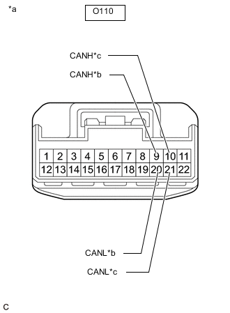
*a Front view of wire harness connector
(to No. 8 CAN Junction Connector)
*b to No. 6 CAN Junction Connector *c to Network Gateway ECU Disconnect the O110 No. 8 CAN junction connector.
-
Measure the resistance according to the value(s) in the table below.
Standard Resistance Tester Connection Condition Specified Condition Connected to O110-9 (CANH) - O110-20 (CANL) Cable disconnected from negative (-) battery terminal 108 to 132 Ω No. 6 CAN junction connector O110-10 (CANH) - O110-21 (CANL) Cable disconnected from negative (-) battery terminal 108 to 132 Ω Network gateway ECU Result Result Proceed to OK A NG (Network gateway ECU main lines) B NG (No. 6 CAN junction connector main lines) C
A
REPLACE NO. 8 CAN JUNCTION CONNECTOR
B
REPAIR OR REPLACE CAN MAIN BUS LINES OR CONNECTOR (NETWORK GATEWAY ECU - NO. 8 CAN JUNCTION CONNECTOR)
C
-
-
CHECK FOR OPEN IN SUB BUS MAIN LINES (NO. 6 CAN JUNCTION CONNECTOR)
-
Reconnect the O110 No. 8 CAN junction connector.
-
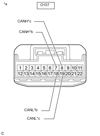
*a Front view of wire harness connector
(to No. 6 CAN Junction Connector)
*b to No. 8 CAN Junction Connector *c to No. 11 CAN Junction Connector Disconnect the O107 No. 6 CAN junction connector.
-
Measure the resistance according to the value(s) in the table below.
Standard Resistance Tester Connection Condition Specified Condition Connected to O107-7 (CANH) - O107-18 (CANL) Cable disconnected from negative (-) battery terminal 108 to 132 Ω No. 8 CAN junction connector O107-8 (CANH) - O107-19 (CANL) Cable disconnected from negative (-) battery terminal 108 to 132 Ω No. 11 CAN junction connector Result Result Proceed to OK A NG (No. 8 CAN junction connector main lines) B NG (No. 11 CAN junction connector main lines) C
A
REPLACE NO. 6 CAN JUNCTION CONNECTOR
B
REPAIR OR REPLACE CAN MAIN BUS LINES OR CONNECTOR (NO. 6 CAN JUNCTION CONNECTOR - NO. 8 CAN JUNCTION CONNECTOR)
C
-
-
CHECK FOR OPEN IN SUB BUS MAIN LINES (NO. 11 CAN JUNCTION CONNECTOR)
-
Reconnect the O107 No. 6 CAN junction connector.
-
*a Front view of wire harness connector
(to No. 11 CAN Junction Connector)
*b to No. 6 CAN Junction Connector *c to No. 9 CAN Junction Connector Disconnect the W13 No. 11 CAN junction connector.
-
Measure the resistance according to the value(s) in the table below.
Standard Resistance Tester Connection Condition Specified Condition Connected to W13-1 (CANH) - W13-7 (CANL) Cable disconnected from negative (-) battery terminal 108 to 132 Ω No. 6 CAN junction connector W13-2 (CANH) - W13-8 (CANL) Cable disconnected from negative (-) battery terminal 108 to 132 Ω No. 9 CAN junction connector Result Result Proceed to OK A NG (No. 6 CAN junction connector main lines) B NG (No. 9 CAN junction connector main lines) C
A
REPLACE NO. 11 CAN JUNCTION CONNECTOR
B
REPAIR OR REPLACE CAN MAIN BUS LINES OR CONNECTOR (NO. 6 CAN JUNCTION CONNECTOR - NO. 11 CAN JUNCTION CONNECTOR)
C
-
-
CHECK FOR OPEN IN SUB BUS MAIN LINES (NO. 9 CAN JUNCTION CONNECTOR)
-
Reconnect the W13 No. 11 CAN junction connector.
-
*a Front view of wire harness connector
(to No. 9 CAN Junction Connector)
*b to No. 11 CAN Junction Connector *c to No. 2 CAN Junction Terminal Disconnect the U53 No. 9 CAN junction connector.
-
Measure the resistance according to the value(s) in the table below.
Standard Resistance Tester Connection Condition Specified Condition Connected to U53-1 (CANH) - U53-12 (CANL) Cable disconnected from negative (-) battery terminal 108 to 132 Ω No. 11 CAN junction connector U53-2 (CANH) - U53-13 (CANL) Cable disconnected from negative (-) battery terminal 108 to 132 Ω No. 2 CAN junction terminal Result Result Proceed to OK A NG (No. 11 CAN junction connector main lines) B NG (No. 2 CAN junction terminal main lines) C
A
REPLACE NO. 9 CAN JUNCTION CONNECTOR
B
REPAIR OR REPLACE CAN MAIN BUS LINES OR CONNECTOR (NO. 9 CAN JUNCTION CONNECTOR - NO. 11 CAN JUNCTION CONNECTOR)
C
REPAIR OR REPLACE CAN MAIN BUS LINES OR CONNECTOR (NO. 9 CAN JUNCTION CONNECTOR - NO. 2 CAN JUNCTION TERMINAL)
-
-
CHECK FOR SHORT IN SUB BUS LINES (NETWORK GATEWAY ECU)
-
*a Front view of wire harness connector
(to Network Gateway ECU)
Disconnect the O46 network gateway ECU connector.
-
Measure the resistance according to the value(s) in the table below.
Standard Resistance Tester Connection Condition Specified Condition O46-13 (CA2H) - O46-12 (CA2L) Cable disconnected from negative (-) battery terminal 108 to 132 Ω Result Result OK NG
OK
REPLACE NETWORK GATEWAY ECU Click here
NG
-
-
CHECK FOR SHORT IN SUB BUS LINES (NO. 2 CAN JUNCTION TERMINAL)
-
Reconnect the O46 network gateway ECU connector.
-
*a Front view of wire harness connector
(to No. 2 CAN Junction Terminal)
Disconnect the O102 No. 2 CAN junction terminal connector.
-
Measure the resistance according to the value(s) in the table below.
Standard Resistance Tester Connection Condition Specified Condition O102-3 (CANH) - O102-2 (CANL) Cable disconnected from negative (-) battery terminal 108 to 132 Ω Result Result OK NG
OK
REPLACE NO. 2 CAN JUNCTION TERMINAL
NG
-
-
CHECK FOR SHORT IN SUB BUS LINES (NO. 8 CAN JUNCTION CONNECTOR)
-
Reconnect the O102 No. 2 CAN junction terminal connector.
-
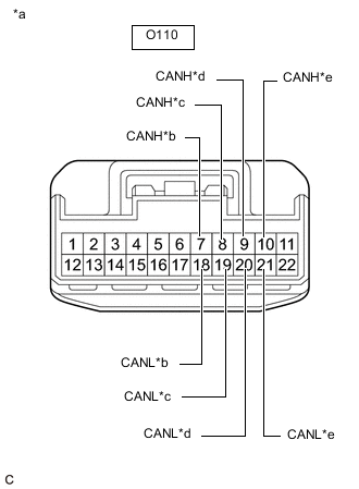
*a Front view of wire harness connector
(to No. 8 CAN Junction Connector)
*b to Absorber Control ECU
(w/ AVS System)
*c Driving Support ECU Assembly
(w/ Pre-crash Safety System)
*d to No. 6 CAN Junction Connector *e to Network Gateway ECU Disconnect the O110 No. 8 CAN junction connector.
-
Measure the resistance according to the value(s) in the table below.
Standard Resistance Tester Connection Condition Specified Condition Connected to O110-7 (CANH) - O110-18 (CANL) Cable disconnected from negative (-) battery terminal 200 Ω or higher Absorber control ECU*1 O110-8 (CANH) - O110-19 (CANL) Cable disconnected from negative (-) battery terminal 200 Ω or higher Driving support ECU assembly*2 O110-9 (CANH) - O110-20 (CANL) Cable disconnected from negative (-) battery terminal 108 to 132 Ω No. 6 CAN junction connector O110-10 (CANH) - O110-21 (CANL) Cable disconnected from negative (-) battery terminal 108 to 132 Ω Network gateway ECU
-
*1: w/ AVS System
-
*2: w/ Pre-crash Safety System
Result Result Proceed to OK A NG (Network gateway ECU main lines) B NG (ECU or sensor branch lines) C NG (No. 6 CAN junction connector main lines) D -
A
REPLACE NO. 8 CAN JUNCTION CONNECTOR
B
REPAIR OR REPLACE CAN MAIN BUS LINES OR CONNECTOR (NETWORK GATEWAY ECU - NO. 8 CAN JUNCTION CONNECTOR)
C
GO TO STEP 38 Click here
D
-
-
CHECK FOR SHORT IN SUB BUS LINES (NO. 6 CAN JUNCTION CONNECTOR)
-
Reconnect the O110 No. 8 CAN junction connector.
-
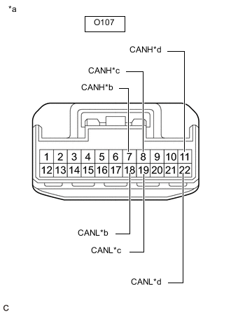
*a Front view of wire harness connector
(to No. 6 CAN Junction Connector)
*b to No. 8 CAN Junction Connector *c to No. 11 CAN Junction Connector *d to Clearance Warning ECU Assembly
(w/ LEXUS Parking Assist-sensor System)
Disconnect the O107 No. 6 CAN junction connector.
-
Measure the resistance according to the value(s) in the table below.
Standard Resistance Tester Connection Condition Specified Condition Connected to O107-7 (CANH) - O107-18 (CANL) Cable disconnected from negative (-) battery terminal 108 to 132 Ω No. 8 CAN junction connector O107-8 (CANH) - O107-19 (CANL) Cable disconnected from negative (-) battery terminal 108 to 132 Ω No. 11 CAN junction connector O107-11 (CANH) - O107-22 (CANL) Cable disconnected from negative (-) battery terminal 200 Ω or higher Clearance warning ECU assembly*
-
*: w/ LEXUS Parking Assist-sensor System
Result Result Proceed to OK A NG (No. 8 CAN junction connector main lines) B NG (ECU or sensor branch lines) C NG (No. 11 CAN junction connector main lines) D -
A
REPLACE NO. 6 CAN JUNCTION CONNECTOR
B
REPAIR OR REPLACE CAN MAIN BUS LINES OR CONNECTOR (NO. 6 CAN JUNCTION CONNECTOR - NO. 8 CAN JUNCTION CONNECTOR)
C
GO TO STEP 38 Click here
D
-
-
CHECK FOR SHORT IN SUB BUS LINES (NO. 11 CAN JUNCTION CONNECTOR)
-
Reconnect the O107 No. 6 CAN junction connector.
-
*a Front view of wire harness connector
(to No. 11 CAN Junction Connector)
*b to No. 6 CAN Junction Connector *c to No. 9 CAN Junction Connector *d to Lane Departure Warning Camera
(w/ Lane Departure Alert System)
Disconnect the W13 No. 11 CAN junction connector.
-
Measure the resistance according to the value(s) in the table below.
Standard Resistance Tester Connection Condition Specified Condition Connected to W13-1 (CANH) - W13-7 (CANL) Cable disconnected from negative (-) battery terminal 108 to 132 Ω No. 6 CAN junction connector W13-2 (CANH) - W13-8 (CANL) Cable disconnected from negative (-) battery terminal 108 to 132 Ω No. 9 CAN junction connector W13-3 (CANH) - W13-9 (CANL) Cable disconnected from negative (-) battery terminal 200 Ω or higher Lane departure warning camera*
-
*: w/ Lane Departure Alert System
Result Result Proceed to OK A NG (No. 6 CAN junction connector main lines) B NG (ECU or sensor branch lines) C NG (No. 9 CAN junction connector main lines) D -
A
REPLACE NO. 11 CAN JUNCTION CONNECTOR
B
REPAIR OR REPLACE CAN MAIN BUS LINES OR CONNECTOR (NO. 6 CAN JUNCTION CONNECTOR - NO. 11 CAN JUNCTION CONNECTOR)
C
GO TO STEP 38 Click here
D
-
-
CHECK FOR SHORT IN SUB BUS LINES (NO. 9 CAN JUNCTION CONNECTOR)
-
Reconnect the W13 No. 11 CAN junction connector.
-
*a Front view of wire harness connector
(to No. 9 CAN Junction Connector)
*b to No. 11 CAN Junction Connector *c to No. 2 CAN Junction Terminal *d to Blind Spot Monitor Sensor LH
(w/ Blind Spot Monitor System)
Disconnect the U53 No. 9 CAN junction connector.
-
Measure the resistance according to the value(s) in the table below.
Standard Resistance Tester Connection Condition Specified Condition Connected to U53-1 (CANH) - U53-12 (CANL) Cable disconnected from negative (-) battery terminal 108 to 132 Ω No. 11 CAN junction connector U53-2 (CANH) - U53-13 (CANL) Cable disconnected from negative (-) battery terminal 108 to 132 Ω No. 2 CAN junction terminal U53-3 (CANH) - U53-14 (CANL) Cable disconnected from negative (-) battery terminal 200 Ω or higher Blind spot monitor sensor LH*
-
*: w/ Blind Spot Monitor System
Result Result Proceed to OK A NG (No. 11 CAN junction connector main lines) B NG (ECU or sensor branch lines) C NG (No. 2 CAN junction terminal main lines) D -
A
REPLACE NO. 9 CAN JUNCTION CONNECTOR
B
REPAIR OR REPLACE CAN MAIN BUS LINES OR CONNECTOR (NO. 9 CAN JUNCTION CONNECTOR - NO. 11 CAN JUNCTION CONNECTOR)
D
REPAIR OR REPLACE CAN MAIN BUS LINES OR CONNECTOR (NO. 9 CAN JUNCTION CONNECTOR - NO. 2 CAN JUNCTION TERMINAL)
C
-
-
CHECK FOR SHORT IN SUB BUS LINES (ECU, SENSOR)
-
Reconnect all wire harness connectors.
-
Disconnect the connector that includes terminals CANH and CANL from the ECU or sensor to which the short circuited branch line is connected.
-
*a Component with harness connected
(Network Gateway ECU)
Measure the resistance according to the value(s) in the table below.
Standard Resistance Tester Connection Condition Specified Condition O46-13 (CA2H) - O46-12 (CA2L) Cable disconnected from negative (-) battery terminal 54 to 69 Ω Tech Tips
If the resistance becomes normal (between 54 and 69 Ω) when the connector is disconnected from the ECU or sensor, there may be a short in the ECU or sensor.
Result Result OK NG
OK
REPLACE CORRESPONDING ECU OR SENSOR
NG
REPAIR OR REPLACE CORRESPONDING ECU OR SENSOR BRANCH LINES OR CONNECTOR
-
-
CHECK FOR SHORT IN SUB BUS LINE (NO. 8 CAN JUNCTION CONNECTOR)
-
Disconnect the O110 No. 8 CAN junction connector.
-
Measure the resistance according to the value(s) in the table below.
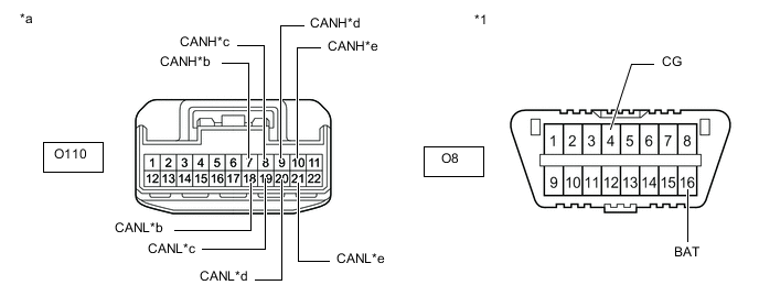
*1 DLC3 - - *a Front view of wire harness connector
(to No. 8 CAN Junction Connector)
*b to Absorber Control ECU
(w/ AVS System)
*c Driving Support ECU Assembly
(w/ Pre-crash Safety System)
*d to No. 6 CAN Junction Connector *e to Network Gateway ECU - - Standard Resistance Tester Connection Condition Specified Condition Result Connected to O110-7 (CANH) - O8-4 (CG) Cable disconnected from negative (-) battery terminal 200 Ω or higher Below 200 Ω: CANH short to ground Absorber control ECU*1 O110-18 (CANL) - O8-4 (CG) Cable disconnected from negative (-) battery terminal 200 Ω or higher Below 200 Ω: CANL short to ground O110-8 (CANH) - O8-4 (CG) Cable disconnected from negative (-) battery terminal 200 Ω or higher Below 200 Ω: CANH short to ground Driving support ECU assembly*2 O110-19 (CANL) - O8-4 (CG) Cable disconnected from negative (-) battery terminal 200 Ω or higher Below 200 Ω: CANL short to ground O110-9 (CANH) - O8-4 (CG) Cable disconnected from negative (-) battery terminal 200 Ω or higher Below 200 Ω: CANH short to ground No. 6 CAN junction connector O110-20 (CANL) - O8-4 (CG) Cable disconnected from negative (-) battery terminal 200 Ω or higher Below 200 Ω: CANL short to ground O110-10 (CANH) - O8-4 (CG) Cable disconnected from negative (-) battery terminal 200 Ω or higher Below 200 Ω: CANH short to ground Network gateway ECU O110-21 (CANL) - O8-4 (CG) Cable disconnected from negative (-) battery terminal 200 Ω or higher Below 200 Ω: CANL short to ground O110-7 (CANH) - O8-16 (BAT) Cable disconnected from negative (-) battery terminal 6 kΩ or higher Below 6 kΩ: CANH +B short Absorber control ECU*1 O110-18 (CANL) - O8-16 (BAT) Cable disconnected from negative (-) battery terminal 6 kΩ or higher Below 6 kΩ: CANL +B short O110-8 (CANH) - O8-16 (BAT) Cable disconnected from negative (-) battery terminal 6 kΩ or higher Below 6 kΩ: CANH +B short Driving support ECU assembly*2 O110-19 (CANL) - O8-16 (BAT) Cable disconnected from negative (-) battery terminal 6 kΩ or higher Below 6 kΩ: CANL +B short O110-9 (CANH) - O8-16 (BAT) Cable disconnected from negative (-) battery terminal 6 kΩ or higher Below 6 kΩ: CANH +B short No. 6 CAN junction connector O110-20 (CANL) - O8-16 (BAT) Cable disconnected from negative (-) battery terminal 6 kΩ or higher Below 6 kΩ: CANL +B short O110-10 (CANH) - O8-16 (BAT) Cable disconnected from negative (-) battery terminal 6 kΩ or higher Below 6 kΩ: CANH +B short Network gateway ECU O110-21 (CANL) - O8-16 (BAT) Cable disconnected from negative (-) battery terminal 6 kΩ or higher Below 6 kΩ: CANL +B short
-
*1: w/ AVS System
-
*2: w/ Pre-crash Safety System
Tech Tips
-
It is only necessary to perform the inspection in the above table for the result (short circuit) that was obtained in the Check Sub Bus inspection.
-
Find the necessary inspection from the Result column that matches the result in the Result column from the Check Sub Bus inspection.
Result Result Proceed to OK A NG (Network gateway ECU main line) B NG (ECU or sensor branch line) C NG (No. 6 CAN junction connector main line) D -
A
REPLACE NO. 8 CAN JUNCTION CONNECTOR
C
GO TO STEP 44 Click here
D
CHECK FOR SHORT IN SUB BUS LINE (NO. 6 CAN JUNCTION CONNECTOR) Click here
B
-
-
CHECK FOR SHORT IN SUB BUS LINE (NETWORK GATEWAY ECU)
-
Reconnect the O110 No. 8 CAN junction connector.
-
*a Front view of wire harness connector
(to Network Gateway ECU)
Disconnect the O46 network gateway ECU connector.
-
Measure the resistance according to the value(s) in the table below.
Standard Resistance Tester Connection Condition Specified Condition Result O46-13 (CA2H) - O46-4 (GND) Cable disconnected from negative (-) battery terminal 200 Ω or higher Below 200 Ω: CANH short to ground O46-12 (CA2L) - O46-4 (GND) Cable disconnected from negative (-) battery terminal 200 Ω or higher Below 200 Ω: CANL short to ground O46-13 (CA2H) - O46-2 (BATT) Cable disconnected from negative (-) battery terminal 6 kΩ or higher Below 6 kΩ: CANH +B short O46-12 (CA2L) - O46-2 (BATT) Cable disconnected from negative (-) battery terminal 6 kΩ or higher Below 6 kΩ: CANL +B short Tech Tips
-
It is only necessary to perform the inspection in the above table for the result (short circuit) that was obtained in the Check Sub Bus inspection.
-
Find the necessary inspection from the Result column that matches the result in the Result column from the Check Sub Bus inspection.
Result Result OK NG -
OK
REPLACE NETWORK GATEWAY ECU Click here
NG
REPAIR OR REPLACE CAN MAIN BUS LINE OR CONNECTOR (NETWORK GATEWAY ECU - NO. 8 CAN JUNCTION CONNECTOR)
-
-
CHECK FOR SHORT IN SUB BUS LINE (NO. 6 CAN JUNCTION CONNECTOR)
-
Reconnect the O110 No. 8 CAN junction connector.
-
Disconnect the O107 No. 6 CAN junction connector.
-
Measure the resistance according to the value(s) in the table below.
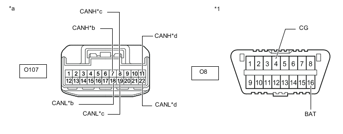
*1 DLC3 - - *a Front view of wire harness connector
(to No. 6 CAN Junction Connector)
*b to No. 8 CAN Junction Connector *c to No. 11 CAN Junction Connector *d to Clearance Warning ECU Assembly
(w/ LEXUS Parking Assist-sensor System)
Standard Resistance Tester Connection Condition Specified Condition Result Connected to O107-7 (CANH) - O8-4 (CG) Cable disconnected from negative (-) battery terminal 200 Ω or higher Below 200 Ω: CANH short to ground No. 8 CAN junction connector O107-18 (CANL) - O8-4 (CG) Cable disconnected from negative (-) battery terminal 200 Ω or higher Below 200 Ω: CANL short to ground O107-8 (CANH) - O8-4 (CG) Cable disconnected from negative (-) battery terminal 200 Ω or higher Below 200 Ω: CANH short to ground No. 11 CAN junction connector O107-19 (CANL) - O8-4 (CG) Cable disconnected from negative (-) battery terminal 200 Ω or higher Below 200 Ω: CANL short to ground O107-11 (CANH) - O8-4 (CG) Cable disconnected from negative (-) battery terminal 200 Ω or higher Below 200 Ω: CANH short to ground Clearance warning ECU assembly* O107-22 (CANL) - O8-4 (CG) Cable disconnected from negative (-) battery terminal 200 Ω or higher Below 200 Ω: CANL short to ground O107-7 (CANH) - O8-16 (BAT) Cable disconnected from negative (-) battery terminal 6 kΩ or higher Below 6 kΩ: CANH +B short No. 8 CAN junction connector O107-18 (CANL) - O8-16 (BAT) Cable disconnected from negative (-) battery terminal 6 kΩ or higher Below 6 kΩ: CANL +B short O107-8 (CANH) - O8-16 (BAT) Cable disconnected from negative (-) battery terminal 6 kΩ or higher Below 6 kΩ: CANH +B short No. 11 CAN junction connector O107-19 (CANL) - O8-16 (BAT) Cable disconnected from negative (-) battery terminal 6 kΩ or higher Below 6 kΩ: CANL +B short O107-11 (CANH) - O8-16 (BAT) Cable disconnected from negative (-) battery terminal 6 kΩ or higher Below 6 kΩ: CANH +B short Clearance warning ECU assembly* O107-22 (CANL) - O8-16 (BAT) Cable disconnected from negative (-) battery terminal 6 kΩ or higher Below 6 kΩ: CANL +B short
-
*: w/ LEXUS Parking Assist-sensor System
Tech Tips
-
It is only necessary to perform the inspection in the above table for the result (short circuit) that was obtained in the Check Sub Bus inspection.
-
Find the necessary inspection from the Result column that matches the result in the Result column from the Check Sub Bus inspection.
Result Result Proceed to OK A NG (ECU or sensor branch line) B NG (No. 8 CAN junction connector main line) C NG (No. 11 CAN junction connector main line) D -
A
REPLACE NO. 6 CAN JUNCTION CONNECTOR
B
GO TO STEP 44 Click here
C
REPAIR OR REPLACE CAN MAIN BUS LINE OR CONNECTOR (NO. 6 CAN JUNCTION CONNECTOR - NO. 8 CAN JUNCTION CONNECTOR)
D
-
-
CHECK FOR SHORT IN SUB BUS LINE (NO. 11 CAN JUNCTION CONNECTOR)
-
Reconnect the O107 No. 6 CAN junction connector.
-
Disconnect the W13 No. 11 CAN junction connector.
-
Measure the resistance according to the value(s) in the table below.
*1 DLC3 - - *a Front view of wire harness connector
(to No. 11 CAN Junction Connector)
*b to No. 6 CAN Junction Connector *c to No. 9 CAN Junction Connector *d to Lane Departure Warning Camera
(w/ Lane Departure Alert System)
Standard Resistance Tester Connection Condition Specified Condition Result Connected to W13-1 (CANH) - O8-4 (CG) Cable disconnected from negative (-) battery terminal 200 Ω or higher Below 200 Ω: CANH short to ground No. 6 CAN junction connector W13-7 (CANL) - O8-4 (CG) Cable disconnected from negative (-) battery terminal 200 Ω or higher Below 200 Ω: CANL short to ground W13-2 (CANH) - O8-4 (CG) Cable disconnected from negative (-) battery terminal 200 Ω or higher Below 200 Ω: CANH short to ground No. 9 CAN junction connector W13-8 (CANL) - O8-4 (CG) Cable disconnected from negative (-) battery terminal 200 Ω or higher Below 200 Ω: CANL short to ground W13-3 (CANH) - O8-4 (CG) Cable disconnected from negative (-) battery terminal 200 Ω or higher Below 200 Ω: CANH short to ground Lane departure warning camera* W13-9 (CANL) - O8-4 (CG) Cable disconnected from negative (-) battery terminal 200 Ω or higher Below 200 Ω: CANL short to ground W13-1 (CANH) - O8-16 (BAT) Cable disconnected from negative (-) battery terminal 6 kΩ or higher Below 6 kΩ: CANH +B short No. 6 CAN junction connector W13-7 (CANL) - O8-16 (BAT) Cable disconnected from negative (-) battery terminal 6 kΩ or higher Below 6 kΩ: CANL +B short W13-2 (CANH) - O8-16 (BAT) Cable disconnected from negative (-) battery terminal 6 kΩ or higher Below 6 kΩ: CANH +B short No. 9 CAN junction connector W13-8 (CANL) - O8-16 (BAT) Cable disconnected from negative (-) battery terminal 6 kΩ or higher Below 6 kΩ: CANL +B short W13-3 (CANH) - O8-16 (BAT) Cable disconnected from negative (-) battery terminal 6 kΩ or higher Below 6 kΩ: CANH +B short Lane departure warning camera* W13-9 (CANL) - O8-16 (BAT) Cable disconnected from negative (-) battery terminal 6 kΩ or higher Below 6 kΩ: CANL +B short
-
*: w/ Lane Departure Alert System
Tech Tips
-
It is only necessary to perform the inspection in the above table for the result (short circuit) that was obtained in the Check Sub Bus inspection.
-
Find the necessary inspection from the Result column that matches the result in the Result column from the Check Sub Bus inspection.
Result Result Proceed to OK A NG (ECU or sensor branch line) B NG (No. 6 CAN junction connector main line) C NG (No. 9 CAN junction connector main line) D -
A
REPLACE NO. 11 CAN JUNCTION CONNECTOR
B
GO TO STEP 44 Click here
C
REPAIR OR REPLACE CAN MAIN BUS LINE OR CONNECTOR (NO. 6 CAN JUNCTION CONNECTOR - NO. 11 CAN JUNCTION CONNECTOR)
D
-
-
CHECK FOR SHORT IN SUB BUS LINE (NO. 9 CAN JUNCTION CONNECTOR)
-
Reconnect the W13 No. 11 CAN junction connector.
-
Disconnect the U53 No. 9 CAN junction connector.
-
Measure the resistance according to the value(s) in the table below.
*1 DLC3 - - *a Front view of wire harness connector
(to No. 9 CAN Junction Connector)
*b to No. 11 CAN Junction Connector *c to No. 2 CAN Junction Terminal *d to Blind Spot Monitor Sensor LH
(w/ Blind Spot Monitor System)
Standard Resistance Tester Connection Condition Specified Condition Result Connected to U53-1 (CANH) - O8-4 (CG) Cable disconnected from negative (-) battery terminal 200 Ω or higher Below 200 Ω: CANH short to ground No. 11 CAN junction connector U53-12 (CANL) - O8-4 (CG) Cable disconnected from negative (-) battery terminal 200 Ω or higher Below 200 Ω: CANL short to ground U53-2 (CANH) - O8-4 (CG) Cable disconnected from negative (-) battery terminal 200 Ω or higher Below 200 Ω: CANH short to ground No. 2 CAN junction terminal U53-13 (CANL) - O8-4 (CG) Cable disconnected from negative (-) battery terminal 200 Ω or higher Below 200 Ω: CANL short to ground U53-3 (CANH) - O8-4 (CG) Cable disconnected from negative (-) battery terminal 200 Ω or higher Below 200 Ω: CANH short to ground Blind spot monitor sensor LH* U53-14 (CANL) - O8-4 (CG) Cable disconnected from negative (-) battery terminal 200 Ω or higher Below 200 Ω: CANL short to ground U53-1 (CANH) - O8-16 (BAT) Cable disconnected from negative (-) battery terminal 6 kΩ or higher Below 6 kΩ: CANH +B short No. 11 CAN junction connector U53-12 (CANL) - O8-16 (BAT) Cable disconnected from negative (-) battery terminal 6 kΩ or higher Below 6 kΩ: CANL +B short U53-2 (CANH) - O8-16 (BAT) Cable disconnected from negative (-) battery terminal 6 kΩ or higher Below 6 kΩ: CANH +B short No. 2 CAN junction terminal U53-13 (CANL) - O8-16 (BAT) Cable disconnected from negative (-) battery terminal 6 kΩ or higher Below 6 kΩ: CANL +B short U53-3 (CANH) - O8-16 (BAT) Cable disconnected from negative (-) battery terminal 6 kΩ or higher Below 6 kΩ: CANH +B short Blind spot monitor sensor LH* U53-14 (CANL) - O8-16 (BAT) Cable disconnected from negative (-) battery terminal 6 kΩ or higher Below 6 kΩ: CANL +B short
-
*: w/ Blind Spot Monitor System
Tech Tips
-
It is only necessary to perform the inspection in the above table for the result (short circuit) that was obtained in the Check Sub Bus inspection.
-
Find the necessary inspection from the Result column that matches the result in the Result column from the Check Sub Bus inspection.
Result Result Proceed to OK A NG (No. 11 CAN junction connector main line) B NG (ECU or sensor branch line) C NG (No. 2 CAN junction terminal main line) D -
A
REPLACE NO. 9 CAN JUNCTION CONNECTOR
B
REPAIR OR REPLACE CAN MAIN BUS LINE OR CONNECTOR (NO. 9 CAN JUNCTION CONNECTOR - NO. 11 CAN JUNCTION CONNECTOR)
D
CHECK FOR SHORT IN SUB BUS LINE (NO. 2 CAN JUNCTION TERMINAL) Click here
C
-
-
CHECK FOR SHORT IN SUB BUS LINE (ECU, SENSOR)
-
Reconnect all wire harness connectors.
-
Disconnect the connector that includes terminals CANH and CANL from the ECU or sensor to which the bus line shorted to +B or shorted to GND is connected.
-
*a Component with harness connected
(Network Gateway ECU)
Measure the resistance according to the value(s) in the table below.
Standard Resistance Tester Connection Condition Specified Condition Result O46-13 (CA2H) - O46-4 (GND) Cable disconnected from negative (-) battery terminal 200 Ω or higher Below 200 Ω: CANH short to ground O46-12 (CA2L) - O46-4 (GND) Cable disconnected from negative (-) battery terminal 200 Ω or higher Below 200 Ω: CANL short to ground O46-13 (CA2H) - O46-2 (BATT) Cable disconnected from negative (-) battery terminal 6 kΩ or higher Below 6 kΩ: CANH +B short O46-12 (CA2L) - O46-2 (BATT) Cable disconnected from negative (-) battery terminal 6 kΩ or higher Below 6 kΩ: CANL +B short Tech Tips
-
It is only necessary to perform the inspection in the above table for the result (short circuit) that was obtained in the Check Sub Bus inspection.
-
If the resistance becomes normal when the connector is disconnected from the ECU or sensor, there may be a short in the ECU or sensor.
-
Find the necessary inspection from the Result column that matches the result in the Result column from the Check Sub Bus inspection.
Result Result OK NG -
OK
REPLACE CORRESPONDING ECU OR SENSOR
NG
REPAIR OR REPLACE CORRESPONDING ECU OR SENSOR BRANCH LINE OR CONNECTOR
-
-
CHECK FOR SHORT IN SUB BUS LINE (NO. 2 CAN JUNCTION TERMINAL)
-
Reconnect the U53 No. 9 CAN junction connector.
-
*1 DLC3 *a Front view of wire harness connector
(to No. 2 CAN Junction Terminal)
Disconnect the O102 No. 2 CAN junction terminal connector.
-
Measure the resistance according to the value(s) in the table below.
Standard Resistance Tester Connection Condition Specified Condition Result O102-3 (CANH) - O8-4 (CG) Cable disconnected from negative (-) battery terminal 200 Ω or higher Below 200 Ω: CANH short to ground O102-2 (CANL) - O8-4 (CG) Cable disconnected from negative (-) battery terminal 200 Ω or higher Below 200 Ω: CANL short to ground O102-3 (CANH) - O8-16 (BAT) Cable disconnected from negative (-) battery terminal 6 kΩ or higher Below 6 kΩ: CANH +B short O102-2 (CANL) - O8-16 (BAT) Cable disconnected from negative (-) battery terminal 6 kΩ or higher Below 6 kΩ: CANL +B short Tech Tips
-
It is only necessary to perform the inspection in the above table for the result (short circuit) that was obtained in the Check Sub Bus inspection.
-
Find the necessary inspection from the Result column that matches the result in the Result column from the Check Sub Bus inspection.
Result Result OK NG -
OK
REPLACE NO. 2 CAN JUNCTION TERMINAL
NG
REPAIR OR REPLACE CAN MAIN BUS LINE OR CONNECTOR (NO. 9 CAN JUNCTION CONNECTOR - NO. 2 CAN JUNCTION TERMINAL)
-