CAN COMMUNICATION SYSTEM, Diagnostic DTC:U1002
| DTC Code | DTC Name |
|---|---|
| U1002 | Lost Communication with Gateway Module (Network Gateway ECU) |
DESCRIPTION
-
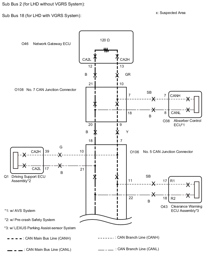
The network gateway ECU will store this DTC when no signals can be received from the ECUs that have been memorized as those that are connected to sub bus 2 (w/o VGRS System) or sub bus 18 (w/ VGRS System).
-
When the network gateway ECU receives a response signal from the ECUs connected to sub bus 2 (w/o VGRS System) or sub bus 18 (w/ VGRS System), the network gateway ECU recognizes and memorizes that the ECU is connected to sub bus 2 (w/o VGRS System) or sub bus 18 (w/ VGRS System). Based on this memorized data, the network gateway ECU monitors for malfunctions in the ECUs connected to sub bus 2 (w/o VGRS System) or sub bus 18 (w/ VGRS System) when communicating with those ECUs. If the network gateway ECU cannot receive response signals from the ECUs that have been memorized as those connected to sub bus 2 (w/o VGRS System) or sub bus 18 (w/ VGRS System), the network gateway ECU determines that a malfunction exists.
| DTC No. | Detection Item | DTC Detection Condition | Trouble Area | Note |
|---|---|---|---|---|
| U1002 | Lost Communication with Gateway Module (Network Gateway ECU) | The network gateway ECU cannot receive signals from all ECUs that have been memorized as those connected to sub bus 2 (w/o VGRS System) or sub bus 18 (w/ VGRS System). |
|
Tech Tips The network gateway ECU stores DTCs when it detects a communication stop or network communication error for ECUs connected to sub bus 2 (w/o VGRS System) or sub bus 18 (w/ VGRS System). |
Tech Tips
This diagnostic procedure is for when DTC U1002 is output by the network gateway ECU (GTS display: Gateway).
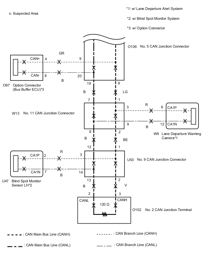
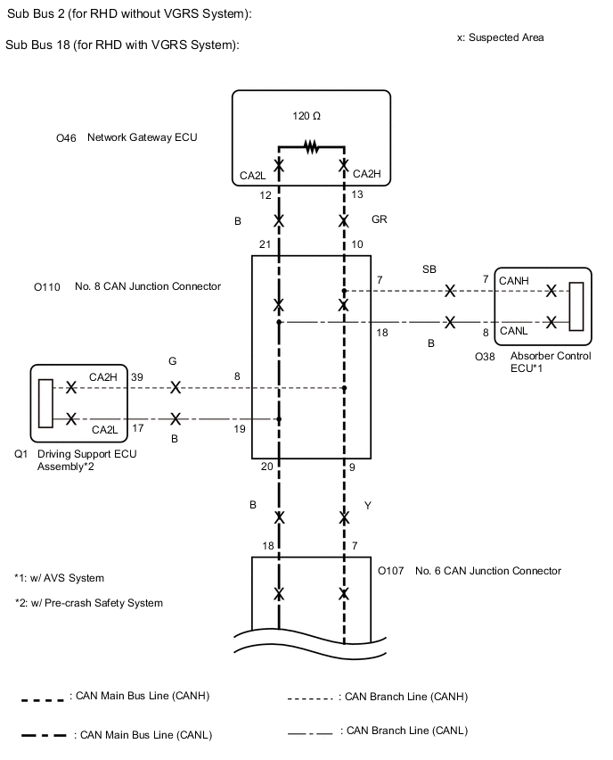
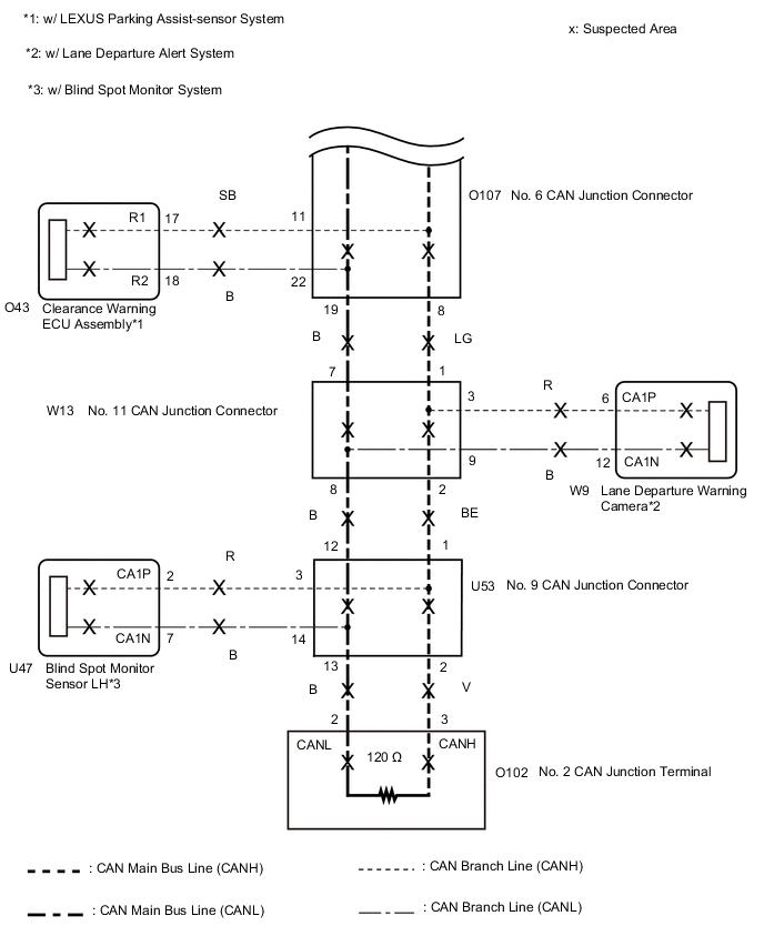
WIRING DIAGRAM
CAUTION / NOTICE / HINT
Note
-
Before measuring the resistance of the CAN bus, turn the engine switch off and leave the vehicle for 1 minute or more without operating the key or any switches, or opening or closing the doors. After that, disconnect the cable from the negative (-) battery terminal and leave the vehicle for 1 minute or more before measuring the resistance.
-
After turning the engine switch off, waiting time may be required before disconnecting the cable from the negative (-) battery terminal. Therefore, make sure to read the disconnecting the cable from the negative (-) battery terminal notices before proceeding with work.
Click here
-
Because the order of diagnosis is important to allow correct diagnosis, make sure to begin troubleshooting using How to Proceed with Troubleshooting when CAN communication system related DTCs are output.
-
After performing repairs, perform the DTC check procedure and confirm that the DTCs are not output again.
-
DTC check procedure: Turn the engine switch on (IG), wait at least 60 seconds, and then drive the vehicle at a speed of 60 km/h (37 mph) or more for 7 seconds or more.
-
After the repair, perform the CAN bus check and check that all the ECUs and sensors connected to the CAN communication system are displayed.
Tech Tips
-
Operating the engine switch, any other switches or a door triggers related ECU and sensor communication on the CAN. This communication will cause the resistance value to change.
-
Even after DTCs are cleared, if a DTC is stored again after driving the vehicle for a while, the malfunction may be occurring due to vibration of the vehicle. In such a case, wiggling the ECUs or wire harness while performing the inspection below may help determine the cause of the malfunction.
PROCEDURE
-
CHECK VEHICLE TYPE
-
Check vehicle type.
Result Result Proceed to for LHD A for RHD B
B 
CHECK SUB BUS Click here
A 
-
-
CHECK SUB BUS
-
Disconnect the cable from the negative (-) battery terminal.
-

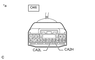
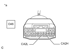
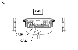
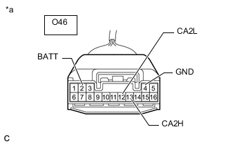
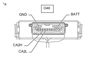
*a Component with harness connected
(Network Gateway ECU)
Measure the resistance according to the value(s) in the table below.
Standard Resistance Tester Connection Condition Specified Condition Result O46-13 (CA2H) - O46-12 (CA2L) Cable disconnected from negative (-) battery terminal 54 to 69 Ω Below 54 Ω: Short circuit between bus lines 70 Ω or higher: Open circuit in main bus lines O46-13 (CA2H) - O46-4 (GND) Cable disconnected from negative (-) battery terminal 200 Ω or higher Below 200 Ω: CANH short to ground O46-12 (CA2L) - O46-4 (GND) Cable disconnected from negative (-) battery terminal 200 Ω or higher Below 200 Ω: CANL short to ground O46-13 (CA2H) - O46-2 (BATT) Cable disconnected from negative (-) battery terminal 6 kΩ or higher Below 6 kΩ: CANH +B short O46-12 (CA2L) - O46-2 (BATT) Cable disconnected from negative (-) battery terminal 6 kΩ or higher Below 6 kΩ: CANL +B short Result Result Proceed to OK A Open circuit in CAN main bus lines B Short circuit between bus lines C
-
Short to ground
-
+B short
D -
B
CHECK FOR OPEN IN SUB BUS MAIN LINES (NETWORK GATEWAY ECU) Click here
C
CHECK FOR SHORT IN SUB BUS LINES (NETWORK GATEWAY ECU) Click here
D
CHECK FOR SHORT IN SUB BUS LINE (NO. 7 CAN JUNCTION CONNECTOR) Click here
A
-
-
CHECK FOR DTC OUTPUT
-
Reconnect the cable to the negative (-) battery terminal.
-
Connect the GTS to the DLC3.
-
Turn the engine switch on (IG).
-
Turn the GTS on.
-
Clear the DTCs.
Body Electrical > Gateway > Clear DTCs -
Turn the engine switch off.
-
Turn the engine switch on (IG).
-
Check for DTCs.
Body Electrical > Gateway > Trouble CodesResult Result Proceed to DTC U1002 is not output from the network gateway ECU (GTS display: Gateway) A DTC U1002 is output from the network gateway ECU (GTS display: Gateway) B
A 
SYMPTOM SIMULATION Click here
B
REPLACE NETWORK GATEWAY ECU Click here
-
-
CHECK FOR OPEN IN SUB BUS MAIN LINES (NETWORK GATEWAY ECU)
-
*a Front view of wire harness connector
(to Network Gateway ECU)
Disconnect the O46 network gateway ECU connector.
-
Measure the resistance according to the value(s) in the table below.
Standard Resistance Tester Connection Condition Specified Condition O46-13 (CA2H) - O46-12 (CA2L) Cable disconnected from negative (-) battery terminal 108 to 132 Ω Result Result OK NG
OK
REPLACE NETWORK GATEWAY ECU Click here
NG
-
-
CHECK FOR OPEN IN SUB BUS MAIN LINES (NO. 2 CAN JUNCTION TERMINAL)
-
Reconnect the O46 network gateway ECU connector.
-
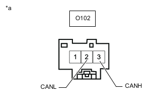
*a Front view of wire harness connector
(to No. 2 CAN Junction Terminal)
Disconnect the O102 No. 2 CAN junction terminal connector.
-
Measure the resistance according to the value(s) in the table below.
Standard Resistance Tester Connection Condition Specified Condition O102-3 (CANH) - O102-2 (CANL) Cable disconnected from negative (-) battery terminal 108 to 132 Ω Result Result OK NG
OK
REPLACE NO. 2 CAN JUNCTION TERMINAL
NG
-
-
CHECK FOR OPEN IN SUB BUS MAIN LINES (NO. 7 CAN JUNCTION CONNECTOR)
-
Reconnect the O102 No. 2 CAN junction terminal connector.
-
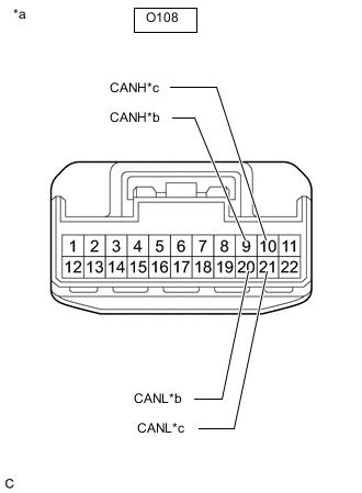
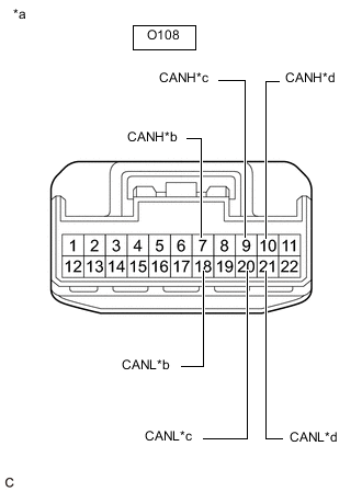
*a Front view of wire harness connector
(to No. 7 CAN Junction Connector)
*b to No. 5 CAN Junction Connector *c to Network Gateway ECU Disconnect the O108 No. 7 CAN junction connector.
-
Measure the resistance according to the value(s) in the table below.
Standard Resistance Tester Connection Condition Specified Condition Connected to O108-9 (CANH) - O108-20 (CANL) Cable disconnected from negative (-) battery terminal 108 to 132 Ω No. 5 CAN junction connector O108-10 (CANH) - O108-21 (CANL) Cable disconnected from negative (-) battery terminal 108 to 132 Ω Network gateway ECU Result Result Proceed to OK A NG (Network gateway ECU main lines) B NG (No. 5 CAN junction connector main lines) C
A
REPLACE NO. 7 CAN JUNCTION CONNECTOR
B
REPAIR OR REPLACE CAN MAIN BUS LINES OR CONNECTOR (NETWORK GATEWAY ECU - NO. 7 CAN JUNCTION CONNECTOR)
C
-
-
CHECK FOR OPEN IN SUB BUS MAIN LINES (NO. 5 CAN JUNCTION CONNECTOR)
-
Reconnect the O108 No. 7 CAN junction connector.
-

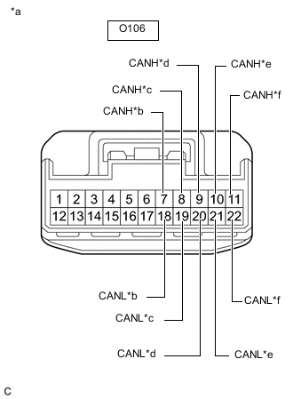
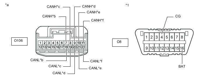
*a Front view of wire harness connector
(to No. 5 CAN Junction Connector)
*b to No. 7 CAN Junction Connector *c to No. 11 CAN Junction Connector Disconnect the O106 No. 5 CAN junction connector.
-
Measure the resistance according to the value(s) in the table below.
Standard Resistance Tester Connection Condition Specified Condition Connected to O106-7 (CANH) - O106-18 (CANL) Cable disconnected from negative (-) battery terminal 108 to 132 Ω No. 7 CAN junction connector O106-8 (CANH) - O106-19 (CANL) Cable disconnected from negative (-) battery terminal 108 to 132 Ω No. 11 CAN junction connector Result Result Proceed to OK A NG (No. 7 CAN junction connector main lines) B NG (No. 11 CAN junction connector main lines) C
A
REPLACE NO. 5 CAN JUNCTION CONNECTOR
B
REPAIR OR REPLACE CAN MAIN BUS LINES OR CONNECTOR (NO. 5 CAN JUNCTION CONNECTOR - NO. 7 CAN JUNCTION CONNECTOR)
C
-
-
CHECK FOR OPEN IN SUB BUS MAIN LINES (NO. 11 CAN JUNCTION CONNECTOR)
-
Reconnect the O106 No. 5 CAN junction connector.
-
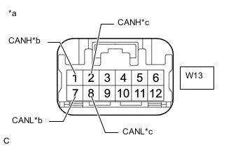
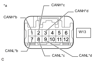
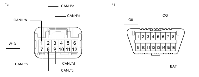
*a Front view of wire harness connector
(to No. 11 CAN Junction Connector)
*b to No. 5 CAN Junction Connector *c to No. 9 CAN Junction Connector Disconnect the W13 No. 11 CAN junction connector.
-
Measure the resistance according to the value(s) in the table below.
Standard Resistance Tester Connection Condition Specified Condition Connected to W13-1 (CANH) - W13-7 (CANL) Cable disconnected from negative (-) battery terminal 108 to 132 Ω No. 5 CAN junction connector W13-2 (CANH) - W13-8 (CANL) Cable disconnected from negative (-) battery terminal 108 to 132 Ω No. 9 CAN junction connector Result Result Proceed to OK A NG (No. 5 CAN junction connector main lines) B NG (No. 9 CAN junction connector main lines) C
A
REPLACE NO. 11 CAN JUNCTION CONNECTOR
B
REPAIR OR REPLACE CAN MAIN BUS LINES OR CONNECTOR (NO. 5 CAN JUNCTION CONNECTOR - NO. 11 CAN JUNCTION CONNECTOR)
C
-
-
CHECK FOR OPEN IN SUB BUS MAIN LINES (NO. 9 CAN JUNCTION CONNECTOR)
-
Reconnect the W13 No. 11 CAN junction connector.
-
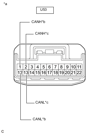
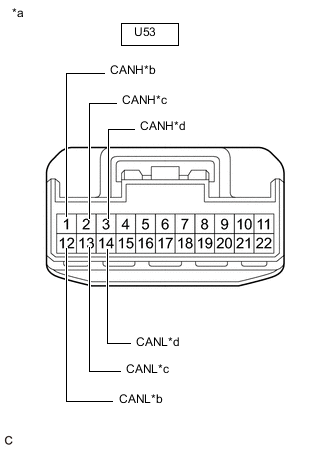
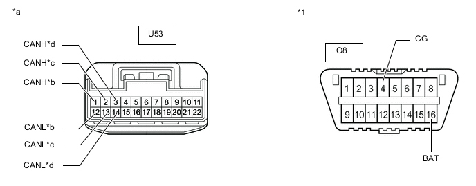
*a Front view of wire harness connector
(to No. 9 CAN Junction Connector)
*b to No. 11 CAN Junction Connector *c to No. 2 CAN Junction Terminal Disconnect the U53 No. 9 CAN junction connector.
-
Measure the resistance according to the value(s) in the table below.
Standard Resistance Tester Connection Condition Specified Condition Connected to U53-1 (CANH) - U53-12 (CANL) Cable disconnected from negative (-) battery terminal 108 to 132 Ω No. 11 CAN junction connector U53-2 (CANH) - U53-13 (CANL) Cable disconnected from negative (-) battery terminal 108 to 132 Ω No. 2 CAN junction terminal Result Result Proceed to OK A NG (No. 11 CAN junction connector main lines) B NG (No. 2 CAN junction terminal main lines) C
A
REPLACE NO. 9 CAN JUNCTION CONNECTOR
B
REPAIR OR REPLACE CAN MAIN BUS LINES OR CONNECTOR (NO. 9 CAN JUNCTION CONNECTOR - NO. 11 CAN JUNCTION CONNECTOR)
C
REPAIR OR REPLACE CAN MAIN BUS LINES OR CONNECTOR (NO. 9 CAN JUNCTION CONNECTOR - NO. 2 CAN JUNCTION TERMINAL)
-
-
CHECK FOR SHORT IN SUB BUS LINES (NETWORK GATEWAY ECU)
-
*a Front view of wire harness connector
(to Network Gateway ECU)
Disconnect the O46 network gateway ECU connector.
-
Measure the resistance according to the value(s) in the table below.
Standard Resistance Tester Connection Condition Specified Condition O46-13 (CA2H) - O46-12 (CA2L) Cable disconnected from negative (-) battery terminal 108 to 132 Ω Result Result OK NG
OK
REPLACE NETWORK GATEWAY ECU Click here
NG
-
-
CHECK FOR SHORT IN SUB BUS LINES (NO. 2 CAN JUNCTION TERMINAL)
-
Reconnect the O46 network gateway ECU connector.
-

*a Front view of wire harness connector
(to No. 2 CAN Junction Terminal)
Disconnect the O102 No. 2 CAN junction terminal connector.
-
Measure the resistance according to the value(s) in the table below.
Standard Resistance Tester Connection Condition Specified Condition O102-3 (CANH) - O102-2 (CANL) Cable disconnected from negative (-) battery terminal 108 to 132 Ω Result Result OK NG
OK
REPLACE NO. 2 CAN JUNCTION TERMINAL
NG
-
-
CHECK FOR SHORT IN SUB BUS LINES (NO. 7 CAN JUNCTION CONNECTOR)
-
Reconnect the O102 No. 2 CAN junction terminal connector.
-
*a Front view of wire harness connector
(to No. 7 CAN Junction Connector)
*b to Absorber Control ECU
(w/ AVS System)
*c to No. 5 CAN Junction Connector *d to Network Gateway ECU Disconnect the O108 No. 7 CAN junction connector.
-
Measure the resistance according to the value(s) in the table below.
Standard Resistance Tester Connection Condition Specified Condition Connected to O108-7 (CANH) - O108-18 (CANL) Cable disconnected from negative (-) battery terminal 200 Ω or higher Absorber control ECU* O108-9 (CANH) - O108-20 (CANL) Cable disconnected from negative (-) battery terminal 108 to 132 Ω No. 5 CAN junction connector O108-10 (CANH) - O108-21 (CANL) Cable disconnected from negative (-) battery terminal 108 to 132 Ω Network gateway ECU
-
*: w/ AVS System
Result Result Proceed to OK A NG (Network gateway ECU main lines) B NG (ECU or sensor branch lines) C NG (No. 5 CAN junction connector main lines) D -
A
REPLACE NO. 7 CAN JUNCTION CONNECTOR
B
REPAIR OR REPLACE CAN MAIN BUS LINES OR CONNECTOR (NETWORK GATEWAY ECU - NO. 7 CAN JUNCTION CONNECTOR)
C
GO TO STEP 16 Click here
D
-
-
CHECK FOR SHORT IN SUB BUS LINES (NO. 5 CAN JUNCTION CONNECTOR)
-
Reconnect the O108 No. 7 CAN junction connector.
-
*a Front view of wire harness connector
(to No. 5 CAN Junction Connector)
*b to No. 7 CAN Junction Connector *c to No. 11 CAN Junction Connector *d to Option Connector (Bus Buffer ECU)
(w/ Option Connector)
*e to Driving Support ECU Assembly
(w/ Pre-crash Safety System)
*f to Clearance Warning ECU Assembly
(w/ LEXUS Parking Assist-sensor System)
Disconnect the O106 No. 5 CAN junction connector.
-
Measure the resistance according to the value(s) in the table below.
Standard Resistance Tester Connection Condition Specified Condition Connected to O106-7 (CANH) - O106-18 (CANL) Cable disconnected from negative (-) battery terminal 108 to 132 Ω No. 7 CAN junction connector O106-8 (CANH) - O106-19 (CANL) Cable disconnected from negative (-) battery terminal 108 to 132 Ω No. 11 CAN junction connector O106-9 (CANH) - O106-20 (CANL) Cable disconnected from negative (-) battery terminal 1 MΩ or higher Option connector (bus buffer ECU)*1 O106-10 (CANH) - O106-21 (CANL) Cable disconnected from negative (-) battery terminal 200 Ω or higher Driving support ECU assembly*2 O106-11 (CANH) - O106-22 (CANL) Cable disconnected from negative (-) battery terminal 200 Ω or higher Clearance warning ECU assembly*3
-
*1: w/ Option Connector
-
*2: w/ Pre-crash Safety System
-
*3: w/ LEXUS Parking Assist-sensor System
Result Result Proceed to OK A NG (No. 7 CAN junction connector main lines) B NG (ECU or sensor branch lines) C NG (No. 11 CAN junction connector main lines) D -
A
REPLACE NO. 5 CAN JUNCTION CONNECTOR
B
REPAIR OR REPLACE CAN MAIN BUS LINES OR CONNECTOR (NO. 5 CAN JUNCTION CONNECTOR - NO. 7 CAN JUNCTION CONNECTOR)
C
GO TO STEP 16 Click here
D
-
-
CHECK FOR SHORT IN SUB BUS LINES (NO. 11 CAN JUNCTION CONNECTOR)
-
Reconnect the O106 No. 5 CAN junction connector.
-
*a Front view of wire harness connector
(to No. 11 CAN Junction Connector)
*b to No. 5 CAN Junction Connector *c to No. 9 CAN Junction Connector *d to Lane Departure Warning Camera
(w/ Lane Departure Alert System)
Disconnect the W13 No. 11 CAN junction connector.
-
Measure the resistance according to the value(s) in the table below.
Standard Resistance Tester Connection Condition Specified Condition Connected to W13-1 (CANH) - W13-7 (CANL) Cable disconnected from negative (-) battery terminal 108 to 132 Ω No. 5 CAN junction connector W13-2 (CANH) - W13-8 (CANL) Cable disconnected from negative (-) battery terminal 108 to 132 Ω No. 9 CAN junction connector W13-3 (CANH) - W13-9 (CANL) Cable disconnected from negative (-) battery terminal 200 Ω or higher Lane departure warning camera*
-
*: w/ Lane Departure Alert System
Result Result Proceed to OK A NG (No. 5 CAN junction connector main lines) B NG (ECU or sensor branch lines) C NG (No. 9 CAN junction connector main lines) D -
A
REPLACE NO. 11 CAN JUNCTION CONNECTOR
B
REPAIR OR REPLACE CAN MAIN BUS LINES OR CONNECTOR (NO. 5 CAN JUNCTION CONNECTOR - NO. 11 CAN JUNCTION CONNECTOR)
C
GO TO STEP 16 Click here
D
-
-
CHECK FOR SHORT IN SUB BUS LINES (NO. 9 CAN JUNCTION CONNECTOR)
-
Reconnect the W13 No. 11 CAN junction connector.
-
*a Front view of wire harness connector
(to No. 9 CAN Junction Connector)
*b to No. 11 CAN Junction Connector *c to No. 2 CAN Junction Terminal *d to Blind Spot Monitor Sensor LH
(w/ Blind Spot Monitor System)
Disconnect the U53 No. 9 CAN junction connector.
-
Measure the resistance according to the value(s) in the table below.
Standard Resistance Tester Connection Condition Specified Condition Connected to U53-1 (CANH) - U53-12 (CANL) Cable disconnected from negative (-) battery terminal 108 to 132 Ω No. 11 CAN junction connector U53-2 (CANH) - U53-13 (CANL) Cable disconnected from negative (-) battery terminal 108 to 132 Ω No. 2 CAN junction terminal U53-3 (CANH) - U53-14 (CANL) Cable disconnected from negative (-) battery terminal 200 Ω or higher Blind spot monitor sensor LH*
-
*: w/ Blind Spot Monitor System
Result Result Proceed to OK A NG (No. 11 CAN junction connector main lines) B NG (ECU or sensor branch lines) C NG (No. 2 CAN junction terminal main lines) D -
A
REPLACE NO. 9 CAN JUNCTION CONNECTOR
B
REPAIR OR REPLACE CAN MAIN BUS LINES OR CONNECTOR (NO. 9 CAN JUNCTION CONNECTOR - NO. 11 CAN JUNCTION CONNECTOR)
D
REPAIR OR REPLACE CAN MAIN BUS LINES OR CONNECTOR (NO. 9 CAN JUNCTION CONNECTOR - NO. 2 CAN JUNCTION TERMINAL)
C
-
-
CHECK FOR SHORT IN SUB BUS LINES (ECU, SENSOR)
-
Reconnect all wire harness connectors.
-
Disconnect the connector that includes terminals CANH and CANL from the ECU or sensor to which the short circuited branch line is connected.
-
*a Component with harness connected
(Network Gateway ECU)
Measure the resistance according to the value(s) in the table below.
Standard Resistance Tester Connection Condition Specified Condition O46-13 (CA2H) - O46-12 (CA2L) Cable disconnected from negative (-) battery terminal 54 to 69 Ω Tech Tips
If the resistance becomes normal (between 54 and 69 Ω) when the connector is disconnected from the ECU or sensor, there may be a short in the ECU or sensor.
Result Result OK NG
OK
REPLACE CORRESPONDING ECU OR SENSOR
NG
REPAIR OR REPLACE CORRESPONDING ECU OR SENSOR BRANCH LINES OR CONNECTOR
-
-
CHECK FOR SHORT IN SUB BUS LINE (NO. 7 CAN JUNCTION CONNECTOR)
-
Disconnect the O108 No. 7 CAN junction connector.
-
Measure the resistance according to the value(s) in the table below.
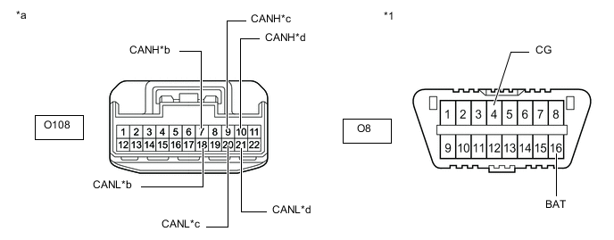
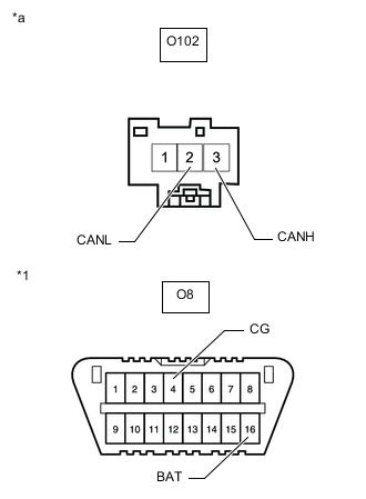
*1 DLC3 - - *a Front view of wire harness connector
(to No. 7 CAN Junction Connector)
*b to Absorber Control ECU
(w/ AVS System)
*c to No. 5 CAN Junction Connector *d to Network Gateway ECU Standard Resistance Tester Connection Condition Specified Condition Result Connected to O108-7 (CANH) - O8-4 (CG) Cable disconnected from negative (-) battery terminal 200 Ω or higher Below 200 Ω: CANH short to ground Absorber control ECU* O108-18 (CANL) - O8-4 (CG) Cable disconnected from negative (-) battery terminal 200 Ω or higher Below 200 Ω: CANL short to ground O108-9 (CANH) - O8-4 (CG) Cable disconnected from negative (-) battery terminal 200 Ω or higher Below 200 Ω: CANH short to ground No. 5 CAN junction connector O108-20 (CANL) - O8-4 (CG) Cable disconnected from negative (-) battery terminal 200 Ω or higher Below 200 Ω: CANL short to ground O108-10 (CANH) - O8-4 (CG) Cable disconnected from negative (-) battery terminal 200 Ω or higher Below 200 Ω: CANH short to ground Network gateway ECU O108-21 (CANL) - O8-4 (CG) Cable disconnected from negative (-) battery terminal 200 Ω or higher Below 200 Ω: CANL short to ground O108-7 (CANH) - O8-16 (BAT) Cable disconnected from negative (-) battery terminal 6 kΩ or higher Below 6 kΩ: CANH +B short Absorber control ECU* O108-18 (CANL) - O8-16 (BAT) Cable disconnected from negative (-) battery terminal 6 kΩ or higher Below 6 kΩ: CANL +B short O108-9 (CANH) - O8-16 (BAT) Cable disconnected from negative (-) battery terminal 6 kΩ or higher Below 6 kΩ: CANH +B short No. 5 CAN junction connector O108-20 (CANL) - O8-16 (BAT) Cable disconnected from negative (-) battery terminal 6 kΩ or higher Below 6 kΩ: CANL +B short O108-10 (CANH) - O8-16 (BAT) Cable disconnected from negative (-) battery terminal 6 kΩ or higher Below 6 kΩ: CANH +B short Network gateway ECU O108-21 (CANL) - O8-16 (BAT) Cable disconnected from negative (-) battery terminal 6 kΩ or higher Below 6 kΩ: CANL +B short
-
*: w/ AVS System
Tech Tips
-
It is only necessary to perform the inspection in the above table for the result (short circuit) that was obtained in the Check Sub Bus inspection.
-
Find the necessary inspection from the Result column that matches the result in the Result column from the Check Sub Bus inspection.
Result Result Proceed to OK A NG (Network gateway ECU main line) B NG (ECU or sensor branch line) C NG (No. 5 CAN junction connector main line) D -
A
REPLACE NO. 7 CAN JUNCTION CONNECTOR
C
GO TO STEP 22 Click here
D
CHECK FOR SHORT IN SUB BUS LINE (NO. 5 CAN JUNCTION CONNECTOR) Click here
B
-
-
CHECK FOR SHORT IN SUB BUS LINE (NETWORK GATEWAY ECU)
-
Reconnect the O108 No. 7 CAN junction connector.
-
*a Front view of wire harness connector
(to Network Gateway ECU)
Disconnect the O46 network gateway ECU connector.
-
Measure the resistance according to the value(s) in the table below.
Standard Resistance Tester Connection Condition Specified Condition Result O46-13 (CA2H) - O46-4 (GND) Cable disconnected from negative (-) battery terminal 200 Ω or higher Below 200 Ω: CANH short to ground O46-12 (CA2L) - O46-4 (GND) Cable disconnected from negative (-) battery terminal 200 Ω or higher Below 200 Ω: CANL short to ground O46-13 (CA2H) - O46-2 (BATT) Cable disconnected from negative (-) battery terminal 6 kΩ or higher Below 6 kΩ: CANH +B short O46-12 (CA2L) - O46-2 (BATT) Cable disconnected from negative (-) battery terminal 6 kΩ or higher Below 6 kΩ: CANL +B short Tech Tips
-
It is only necessary to perform the inspection in the above table for the result (short circuit) that was obtained in the Check Sub Bus inspection.
-
Find the necessary inspection from the Result column that matches the result in the Result column from the Check Sub Bus inspection.
Result Result OK NG -
OK
REPLACE NETWORK GATEWAY ECU Click here
NG
REPAIR OR REPLACE CAN MAIN BUS LINE OR CONNECTOR (NETWORK GATEWAY ECU - NO. 7 CAN JUNCTION CONNECTOR)
-
-
CHECK FOR SHORT IN SUB BUS LINE (NO. 5 CAN JUNCTION CONNECTOR)
-
Reconnect the O108 No. 7 CAN junction connector.
-
Disconnect the O106 No. 5 CAN junction connector.
-
Measure the resistance according to the value(s) in the table below.
*1 DLC3 - - *a Front view of wire harness connector
(to No. 5 CAN Junction Connector)
*b to No. 7 CAN Junction Connector *c to No. 11 CAN Junction Connector *d to Option Connector (Bus Buffer ECU)
(w/ Option Connector)
*e to Driving Support ECU Assembly
(w/ Pre-crash Safety System)
*f to Clearance Warning ECU Assembly
(w/ LEXUS Parking Assist-sensor System)
Standard Resistance Tester Connection Condition Specified Condition Result Connected to O106-7 (CANH) - O8-4 (CG) Cable disconnected from negative (-) battery terminal 200 Ω or higher Below 200 Ω: CANH short to ground No. 7 CAN junction connector O106-18 (CANL) - O8-4 (CG) Cable disconnected from negative (-) battery terminal 200 Ω or higher Below 200 Ω: CANL short to ground O106-8 (CANH) - O8-4 (CG) Cable disconnected from negative (-) battery terminal 200 Ω or higher Below 200 Ω: CANH short to ground No. 11 CAN junction connector O106-19 (CANL) - O8-4 (CG) Cable disconnected from negative (-) battery terminal 200 Ω or higher Below 200 Ω: CANL short to ground O106-9 (CANH) - O8-4 (CG) Cable disconnected from negative (-) battery terminal 200 Ω or higher Below 200 Ω: CANH short to ground Option connector (bus buffer ECU)*1 O106-20 (CANL) - O8-4 (CG) Cable disconnected from negative (-) battery terminal 200 Ω or higher Below 200 Ω: CANL short to ground O106-10 (CANH) - O8-4 (CG) Cable disconnected from negative (-) battery terminal 200 Ω or higher Below 200 Ω: CANH short to ground Driving support ECU assembly*2 O106-21 (CANL) - O8-4 (CG) Cable disconnected from negative (-) battery terminal 200 Ω or higher Below 200 Ω: CANL short to ground O106-11 (CANH) - O8-4 (CG) Cable disconnected from negative (-) battery terminal 200 Ω or higher Below 200 Ω: CANH short to ground Clearance warning ECU assembly*3 O106-22 (CANL) - O8-4 (CG) Cable disconnected from negative (-) battery terminal 200 Ω or higher Below 200 Ω: CANL short to ground O106-7 (CANH) - O8-16 (BAT) Cable disconnected from negative (-) battery terminal 6 kΩ or higher Below 6 kΩ: CANH +B short No. 7 CAN junction connector O106-18 (CANL) - O8-16 (BAT) Cable disconnected from negative (-) battery terminal 6 kΩ or higher Below 6 kΩ: CANL +B short O106-8 (CANH) - O8-16 (BAT) Cable disconnected from negative (-) battery terminal 6 kΩ or higher Below 6 kΩ: CANH +B short No. 11 CAN junction connector O106-19 (CANL) - O8-16 (BAT) Cable disconnected from negative (-) battery terminal 6 kΩ or higher Below 6 kΩ: CANL +B short O106-9 (CANH) - O8-16 (BAT) Cable disconnected from negative (-) battery terminal 6 kΩ or higher Below 6 kΩ: CANH +B short Option connector (bus buffer ECU)*1 O106-20 (CANL) - O8-16 (BAT) Cable disconnected from negative (-) battery terminal 6 kΩ or higher Below 6 kΩ: CANL +B short O106-10 (CANH) - O8-16 (BAT) Cable disconnected from negative (-) battery terminal 6 kΩ or higher Below 6 kΩ: CANH +B short Driving support ECU assembly*2 O106-21 (CANL) - O8-16 (BAT) Cable disconnected from negative (-) battery terminal 6 kΩ or higher Below 6 kΩ: CANL +B short O106-11 (CANH) - O8-16 (BAT) Cable disconnected from negative (-) battery terminal 6 kΩ or higher Below 6 kΩ: CANH +B short Clearance warning ECU assembly*3 O106-22 (CANL) - O8-16 (BAT) Cable disconnected from negative (-) battery terminal 6 kΩ or higher Below 6 kΩ: CANL +B short
-
*1: w/ Option Connector
-
*2: w/ Pre-crash Safety System
-
*3: w/ LEXUS Parking Assist-sensor System
Tech Tips
-
It is only necessary to perform the inspection in the above table for the result (short circuit) that was obtained in the Check Sub Bus inspection.
-
Find the necessary inspection from the Result column that matches the result in the Result column from the Check Sub Bus inspection.
Result Result Proceed to OK A NG (ECU or sensor branch line) B NG (No. 7 CAN junction connector main line) C NG (No. 11 CAN junction connector main line) D -
A
REPLACE NO. 5 CAN JUNCTION CONNECTOR
B
GO TO STEP 22 Click here
C
REPAIR OR REPLACE CAN MAIN BUS LINE OR CONNECTOR (NO. 5 CAN JUNCTION CONNECTOR - NO. 7 CAN JUNCTION CONNECTOR)
D
-
-
CHECK FOR SHORT IN SUB BUS LINE (NO. 11 CAN JUNCTION CONNECTOR)
-
Reconnect the O106 No. 5 CAN junction connector.
-
Disconnect the W13 No. 11 CAN junction connector.
-
Measure the resistance according to the value(s) in the table below.
*1 DLC3 - - *a Front view of wire harness connector
(to No. 11 CAN Junction Connector)
*b to No. 5 CAN Junction Connector *c to No. 9 CAN Junction Connector *d to Lane Departure Warning Camera
(w/ Lane Departure Alert System)
Standard Resistance Tester Connection Condition Specified Condition Result Connected to W13-1 (CANH) - O8-4 (CG) Cable disconnected from negative (-) battery terminal 200 Ω or higher Below 200 Ω: CANH short to ground No. 5 CAN junction connector W13-7 (CANL) - O8-4 (CG) Cable disconnected from negative (-) battery terminal 200 Ω or higher Below 200 Ω: CANL short to ground W13-2 (CANH) - O8-4 (CG) Cable disconnected from negative (-) battery terminal 200 Ω or higher Below 200 Ω: CANH short to ground No. 9 CAN junction connector W13-8 (CANL) - O8-4 (CG) Cable disconnected from negative (-) battery terminal 200 Ω or higher Below 200 Ω: CANL short to ground W13-3 (CANH) - O8-4 (CG) Cable disconnected from negative (-) battery terminal 200 Ω or higher Below 200 Ω: CANH short to ground Lane departure warning camera* W13-9 (CANL) - O8-4 (CG) Cable disconnected from negative (-) battery terminal 200 Ω or higher Below 200 Ω: CANL short to ground W13-1 (CANH) - O8-16 (BAT) Cable disconnected from negative (-) battery terminal 6 kΩ or higher Below 6 kΩ: CANH +B short No. 5 CAN junction connector W13-7 (CANL) - O8-16 (BAT) Cable disconnected from negative (-) battery terminal 6 kΩ or higher Below 6 kΩ: CANL +B short W13-2 (CANH) - O8-16 (BAT) Cable disconnected from negative (-) battery terminal 6 kΩ or higher Below 6 kΩ: CANH +B short No. 9 CAN junction connector W13-8 (CANL) - O8-16 (BAT) Cable disconnected from negative (-) battery terminal 6 kΩ or higher Below 6 kΩ: CANL +B short W13-3 (CANH) - O8-16 (BAT) Cable disconnected from negative (-) battery terminal 6 kΩ or higher Below 6 kΩ: CANH +B short Lane departure warning camera* W13-9 (CANL) - O8-16 (BAT) Cable disconnected from negative (-) battery terminal 6 kΩ or higher Below 6 kΩ: CANL +B short
-
*: w/ Lane Departure Alert System
Tech Tips
-
It is only necessary to perform the inspection in the above table for the result (short circuit) that was obtained in the Check Sub Bus inspection.
-
Find the necessary inspection from the Result column that matches the result in the Result column from the Check Sub Bus inspection.
Result Result Proceed to OK A NG (ECU or sensor branch line) B NG (No. 5 CAN junction connector main line) C NG (No. 9 CAN junction connector main line) D -
A
REPLACE NO. 11 CAN JUNCTION CONNECTOR
B
GO TO STEP 22 Click here
C
REPAIR OR REPLACE CAN MAIN BUS LINE OR CONNECTOR (NO. 5 CAN JUNCTION CONNECTOR - NO. 11 CAN JUNCTION CONNECTOR)
D
-
-
CHECK FOR SHORT IN SUB BUS LINE (NO. 9 CAN JUNCTION CONNECTOR)
-
Reconnect the W13 No. 11 CAN junction connector.
-
Disconnect the U53 No. 9 CAN junction connector.
-
Measure the resistance according to the value(s) in the table below.
*1 DLC3 - - *a Front view of wire harness connector
(to No. 9 CAN Junction Connector)
*b to No. 11 CAN Junction Connector *c to No. 2 CAN Junction Terminal *d to Blind Spot Monitor Sensor LH
(w/ Blind Spot Monitor System)
Standard Resistance Tester Connection Condition Specified Condition Result Connected to U53-1 (CANH) - O8-4 (CG) Cable disconnected from negative (-) battery terminal 200 Ω or higher Below 200 Ω: CANH short to ground No. 11 CAN junction connector U53-12 (CANL) - O8-4 (CG) Cable disconnected from negative (-) battery terminal 200 Ω or higher Below 200 Ω: CANL short to ground U53-2 (CANH) - O8-4 (CG) Cable disconnected from negative (-) battery terminal 200 Ω or higher Below 200 Ω: CANH short to ground No. 2 CAN junction terminal U53-13 (CANL) - O8-4 (CG) Cable disconnected from negative (-) battery terminal 200 Ω or higher Below 200 Ω: CANL short to ground U53-3 (CANH) - O8-4 (CG) Cable disconnected from negative (-) battery terminal 200 Ω or higher Below 200 Ω: CANH short to ground Blind spot monitor sensor LH* U53-14 (CANL) - O8-4 (CG) Cable disconnected from negative (-) battery terminal 200 Ω or higher Below 200 Ω: CANL short to ground U53-1 (CANH) - O8-16 (BAT) Cable disconnected from negative (-) battery terminal 6 kΩ or higher Below 6 kΩ: CANH +B short No. 11 CAN junction connector U53-12 (CANL) - O8-16 (BAT) Cable disconnected from negative (-) battery terminal 6 kΩ or higher Below 6 kΩ: CANL +B short U53-2 (CANH) - O8-16 (BAT) Cable disconnected from negative (-) battery terminal 6 kΩ or higher Below 6 kΩ: CANH +B short No. 2 CAN junction terminal U53-13 (CANL) - O8-16 (BAT) Cable disconnected from negative (-) battery terminal 6 kΩ or higher Below 6 kΩ: CANL +B short U53-3 (CANH) - O8-16 (BAT) Cable disconnected from negative (-) battery terminal 6 kΩ or higher Below 6 kΩ: CANH +B short Blind spot monitor sensor LH* U53-14 (CANL) - O8-16 (BAT) Cable disconnected from negative (-) battery terminal 6 kΩ or higher Below 6 kΩ: CANL +B short
-
*: w/ Blind Spot Monitor System
Tech Tips
-
It is only necessary to perform the inspection in the above table for the result (short circuit) that was obtained in the Check Sub Bus inspection.
-
Find the necessary inspection from the Result column that matches the result in the Result column from the Check Sub Bus inspection.
Result Result Proceed to OK A NG (No. 11 CAN junction connector main line) B NG (ECU or sensor branch line) C NG (No. 2 CAN junction terminal main line) D -
A
REPLACE NO. 9 CAN JUNCTION CONNECTOR
B
REPAIR OR REPLACE CAN MAIN BUS LINE OR CONNECTOR (NO. 9 CAN JUNCTION CONNECTOR - NO. 11 CAN JUNCTION CONNECTOR)
D
CHECK FOR SHORT IN SUB BUS LINE (NO. 2 CAN JUNCTION TERMINAL) Click here
C
-
-
CHECK FOR SHORT IN SUB BUS LINE (ECU, SENSOR)
-
Reconnect all wire harness connectors.
-
Disconnect the connector that includes terminals CANH and CANL from the ECU or sensor to which the bus line shorted to +B or shorted to GND is connected.
-
*a Component with harness connected
(Network Gateway ECU)
Measure the resistance according to the value(s) in the table below.
Standard Resistance Tester Connection Condition Specified Condition Result O46-13 (CA2H) - O46-4 (GND) Cable disconnected from negative (-) battery terminal 200 Ω or higher Below 200 Ω: CANH short to ground O46-12 (CA2L) - O46-4 (GND) Cable disconnected from negative (-) battery terminal 200 Ω or higher Below 200 Ω: CANL short to ground O46-13 (CA2H) - O46-2 (BATT) Cable disconnected from negative (-) battery terminal 6 kΩ or higher Below 6 kΩ: CANH +B short O46-12 (CA2L) - O46-2 (BATT) Cable disconnected from negative (-) battery terminal 6 kΩ or higher Below 6 kΩ: CANL +B short Tech Tips
-
It is only necessary to perform the inspection in the above table for the result (short circuit) that was obtained in the Check Sub Bus inspection.
-
If the resistance becomes normal when the connector is disconnected from the ECU or sensor, there may be a short in the ECU or sensor.
-
Find the necessary inspection from the Result column that matches the result in the Result column from the Check Sub Bus inspection.
Result Result OK NG -
OK
REPLACE CORRESPONDING ECU OR SENSOR
NG
REPAIR OR REPLACE CORRESPONDING ECU OR SENSOR BRANCH LINE OR CONNECTOR
-
-
CHECK FOR SHORT IN SUB BUS LINE (NO. 2 CAN JUNCTION TERMINAL)
-
Reconnect the U53 No. 9 CAN junction connector.
-
*1 DLC3 *a Front view of wire harness connector
(to No. 2 CAN Junction Terminal)
Disconnect the O102 No. 2 CAN junction terminal connector.
-
Measure the resistance according to the value(s) in the table below.
Standard Resistance Tester Connection Condition Specified Condition Result O102-3 (CANH) - O8-4 (CG) Cable disconnected from negative (-) battery terminal 200 Ω or higher Below 200 Ω: CANH short to ground O102-2 (CANL) - O8-4 (CG) Cable disconnected from negative (-) battery terminal 200 Ω or higher Below 200 Ω: CANL short to ground O102-3 (CANH) - O8-16 (BAT) Cable disconnected from negative (-) battery terminal 6 kΩ or higher Below 6 kΩ: CANH +B short O102-2 (CANL) - O8-16 (BAT) Cable disconnected from negative (-) battery terminal 6 kΩ or higher Below 6 kΩ: CANL +B short Tech Tips
-
It is only necessary to perform the inspection in the above table for the result (short circuit) that was obtained in the Check Sub Bus inspection.
-
Find the necessary inspection from the Result column that matches the result in the Result column from the Check Sub Bus inspection.
Result Result OK NG -
OK
REPLACE NO. 2 CAN JUNCTION TERMINAL
NG
REPAIR OR REPLACE CAN MAIN BUS LINE OR CONNECTOR (NO. 9 CAN JUNCTION CONNECTOR - NO. 2 CAN JUNCTION TERMINAL)
-
-
CHECK SUB BUS
-
Disconnect the cable from the negative (-) battery terminal.
-
*a Component with harness connected
(Network Gateway ECU)
Measure the resistance according to the value(s) in the table below.
Standard Resistance Tester Connection Condition Specified Condition Result O46-13 (CA2H) - O46-12 (CA2L) Cable disconnected from negative (-) battery terminal 54 to 69 Ω Below 54 Ω: Short circuit between bus lines 70 Ω or higher: Open circuit in main bus lines O46-13 (CA2H) - O46-4 (GND) Cable disconnected from negative (-) battery terminal 200 Ω or higher Below 200 Ω: CANH short to ground O46-12 (CA2L) - O46-4 (GND) Cable disconnected from negative (-) battery terminal 200 Ω or higher Below 200 Ω: CANL short to ground O46-13 (CA2H) - O46-2 (BATT) Cable disconnected from negative (-) battery terminal 6 kΩ or higher Below 6 kΩ: CANH +B short O46-12 (CA2L) - O46-2 (BATT) Cable disconnected from negative (-) battery terminal 6 kΩ or higher Below 6 kΩ: CANL +B short Result Result Proceed to OK A Open circuit in CAN main bus lines B Short circuit between bus lines C
-
Short to ground
-
+B short
D -
B
CHECK FOR OPEN IN SUB BUS MAIN LINES (NETWORK GATEWAY ECU) Click here
C
CHECK FOR SHORT IN SUB BUS LINES (NETWORK GATEWAY ECU) Click here
D
CHECK FOR SHORT IN SUB BUS LINE (NO. 8 CAN JUNCTION CONNECTOR) Click here
A
-
-
CHECK FOR DTC OUTPUT
-
Reconnect the cable to the negative (-) battery terminal.
-
Connect the GTS to the DLC3.
-
Turn the engine switch on (IG).
-
Turn the GTS on.
-
Clear the DTCs.
Body Electrical > Gateway > Clear DTCs -
Turn the engine switch off.
-
Turn the engine switch on (IG).
-
Check for DTCs.
Body Electrical > Gateway > Trouble CodesResult Result Proceed to DTC U1002 is not output from the network gateway ECU (GTS display: Gateway) A DTC U1002 is output from the network gateway ECU (GTS display: Gateway) B
A
SYMPTOM SIMULATION Click here
B
REPLACE NETWORK GATEWAY ECU Click here
-
-
CHECK FOR OPEN IN SUB BUS MAIN LINES (NETWORK GATEWAY ECU)
-
*a Front view of wire harness connector
(to Network Gateway ECU)
Disconnect the O46 network gateway ECU connector.
-
Measure the resistance according to the value(s) in the table below.
Standard Resistance Tester Connection Condition Specified Condition O46-13 (CA2H) - O46-12 (CA2L) Cable disconnected from negative (-) battery terminal 108 to 132 Ω Result Result OK NG
OK
REPLACE NETWORK GATEWAY ECU Click here
NG
-
-
CHECK FOR OPEN IN SUB BUS MAIN LINES (NO. 2 CAN JUNCTION TERMINAL)
-
Reconnect the O46 network gateway ECU connector.
-
*a Front view of wire harness connector
(to No. 2 CAN Junction Terminal)
Disconnect the O102 No. 2 CAN junction terminal connector.
-
Measure the resistance according to the value(s) in the table below.
Standard Resistance Tester Connection Condition Specified Condition O102-3 (CANH) - O102-2 (CANL) Cable disconnected from negative (-) battery terminal 108 to 132 Ω Result Result OK NG
OK
REPLACE NO. 2 CAN JUNCTION TERMINAL
NG
-
-
CHECK FOR OPEN IN SUB BUS MAIN LINES (NO. 8 CAN JUNCTION CONNECTOR)
-
Reconnect the O102 No. 2 CAN junction terminal connector.
-
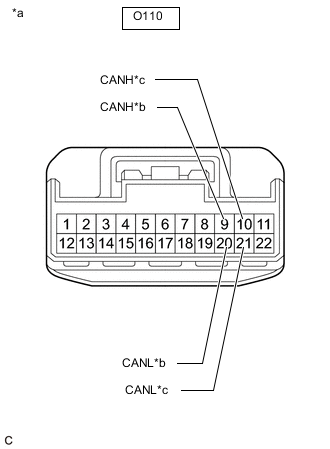
*a Front view of wire harness connector
(to No. 8 CAN Junction Connector)
*b to No. 6 CAN Junction Connector *c to Network Gateway ECU Disconnect the O110 No. 8 CAN junction connector.
-
Measure the resistance according to the value(s) in the table below.
Standard Resistance Tester Connection Condition Specified Condition Connected to O110-9 (CANH) - O110-20 (CANL) Cable disconnected from negative (-) battery terminal 108 to 132 Ω No. 6 CAN junction connector O110-10 (CANH) - O110-21 (CANL) Cable disconnected from negative (-) battery terminal 108 to 132 Ω Network gateway ECU Result Result Proceed to OK A NG (Network gateway ECU main lines) B NG (No. 6 CAN junction connector main lines) C
A
REPLACE NO. 8 CAN JUNCTION CONNECTOR
B
REPAIR OR REPLACE CAN MAIN BUS LINES OR CONNECTOR (NETWORK GATEWAY ECU - NO. 8 CAN JUNCTION CONNECTOR)
C
-
-
CHECK FOR OPEN IN SUB BUS MAIN LINES (NO. 6 CAN JUNCTION CONNECTOR)
-
Reconnect the O110 No. 8 CAN junction connector.
-
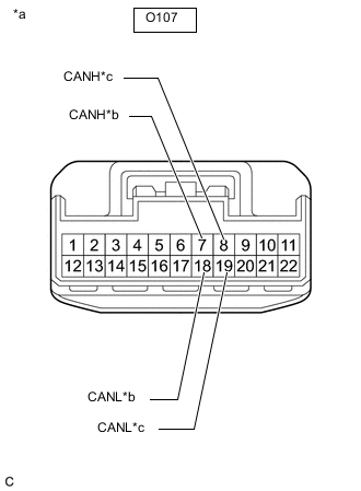
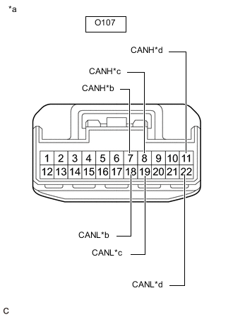
*a Front view of wire harness connector
(to No. 6 CAN Junction Connector)
*b to No. 8 CAN Junction Connector *c to No. 11 CAN Junction Connector Disconnect the O107 No. 6 CAN junction connector.
-
Measure the resistance according to the value(s) in the table below.
Standard Resistance Tester Connection Condition Specified Condition Connected to O107-7 (CANH) - O107-18 (CANL) Cable disconnected from negative (-) battery terminal 108 to 132 Ω No. 8 CAN junction connector O107-8 (CANH) - O107-19 (CANL) Cable disconnected from negative (-) battery terminal 108 to 132 Ω No. 11 CAN junction connector Result Result Proceed to OK A NG (No. 8 CAN junction connector main lines) B NG (No. 11 CAN junction connector main lines) C
A
REPLACE NO. 6 CAN JUNCTION CONNECTOR
B
REPAIR OR REPLACE CAN MAIN BUS LINES OR CONNECTOR (NO. 6 CAN JUNCTION CONNECTOR - NO. 8 CAN JUNCTION CONNECTOR)
C
-
-
CHECK FOR OPEN IN SUB BUS MAIN LINES (NO. 11 CAN JUNCTION CONNECTOR)
-
Reconnect the O107 No. 6 CAN junction connector.
-
*a Front view of wire harness connector
(to No. 11 CAN Junction Connector)
*b to No. 6 CAN Junction Connector *c to No. 9 CAN Junction Connector Disconnect the W13 No. 11 CAN junction connector.
-
Measure the resistance according to the value(s) in the table below.
Standard Resistance Tester Connection Condition Specified Condition Connected to W13-1 (CANH) - W13-7 (CANL) Cable disconnected from negative (-) battery terminal 108 to 132 Ω No. 6 CAN junction connector W13-2 (CANH) - W13-8 (CANL) Cable disconnected from negative (-) battery terminal 108 to 132 Ω No. 9 CAN junction connector Result Result Proceed to OK A NG (No. 6 CAN junction connector main lines) B NG (No. 9 CAN junction connector main lines) C
A
REPLACE NO. 11 CAN JUNCTION CONNECTOR
B
REPAIR OR REPLACE CAN MAIN BUS LINES OR CONNECTOR (NO. 6 CAN JUNCTION CONNECTOR - NO. 11 CAN JUNCTION CONNECTOR)
C
-
-
CHECK FOR OPEN IN SUB BUS MAIN LINES (NO. 9 CAN JUNCTION CONNECTOR)
-
Reconnect the W13 No. 11 CAN junction connector.
-
*a Front view of wire harness connector
(to No. 9 CAN Junction Connector)
*b to No. 11 CAN Junction Connector *c to No. 2 CAN Junction Terminal Disconnect the U53 No. 9 CAN junction connector.
-
Measure the resistance according to the value(s) in the table below.
Standard Resistance Tester Connection Condition Specified Condition Connected to U53-1 (CANH) - U53-12 (CANL) Cable disconnected from negative (-) battery terminal 108 to 132 Ω No. 11 CAN junction connector U53-2 (CANH) - U53-13 (CANL) Cable disconnected from negative (-) battery terminal 108 to 132 Ω No. 2 CAN junction terminal Result Result Proceed to OK A NG (No. 11 CAN junction connector main lines) B NG (No. 2 CAN junction terminal main lines) C
A
REPLACE NO. 9 CAN JUNCTION CONNECTOR
B
REPAIR OR REPLACE CAN MAIN BUS LINES OR CONNECTOR (NO. 9 CAN JUNCTION CONNECTOR - NO. 11 CAN JUNCTION CONNECTOR)
C
REPAIR OR REPLACE CAN MAIN BUS LINES OR CONNECTOR (NO. 9 CAN JUNCTION CONNECTOR - NO. 2 CAN JUNCTION TERMINAL)
-
-
CHECK FOR SHORT IN SUB BUS LINES (NETWORK GATEWAY ECU)
-
*a Front view of wire harness connector
(to Network Gateway ECU)
Disconnect the O46 network gateway ECU connector.
-
Measure the resistance according to the value(s) in the table below.
Standard Resistance Tester Connection Condition Specified Condition O46-13 (CA2H) - O46-12 (CA2L) Cable disconnected from negative (-) battery terminal 108 to 132 Ω Result Result OK NG
OK
REPLACE NETWORK GATEWAY ECU Click here
NG
-
-
CHECK FOR SHORT IN SUB BUS LINES (NO. 2 CAN JUNCTION TERMINAL)
-
Reconnect the O46 network gateway ECU connector.
-
*a Front view of wire harness connector
(to No. 2 CAN Junction Terminal)
Disconnect the O102 No. 2 CAN junction terminal connector.
-
Measure the resistance according to the value(s) in the table below.
Standard Resistance Tester Connection Condition Specified Condition O102-3 (CANH) - O102-2 (CANL) Cable disconnected from negative (-) battery terminal 108 to 132 Ω Result Result OK NG
OK
REPLACE NO. 2 CAN JUNCTION TERMINAL
NG
-
-
CHECK FOR SHORT IN SUB BUS LINES (NO. 8 CAN JUNCTION CONNECTOR)
-
Reconnect the O102 No. 2 CAN junction terminal connector.
-
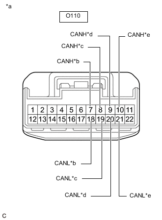
*a Front view of wire harness connector
(to No. 8 CAN Junction Connector)
*b to Absorber Control ECU
(w/ AVS System)
*c Driving Support ECU Assembly
(w/ Pre-crash Safety System)
*d to No. 6 CAN Junction Connector *e to Network Gateway ECU Disconnect the O110 No. 8 CAN junction connector.
-
Measure the resistance according to the value(s) in the table below.
Standard Resistance Tester Connection Condition Specified Condition Connected to O110-7 (CANH) - O110-18 (CANL) Cable disconnected from negative (-) battery terminal 200 Ω or higher Absorber control ECU*1 O110-8 (CANH) - O110-19 (CANL) Cable disconnected from negative (-) battery terminal 200 Ω or higher Driving support ECU assembly*2 O110-9 (CANH) - O110-20 (CANL) Cable disconnected from negative (-) battery terminal 108 to 132 Ω No. 6 CAN junction connector O110-10 (CANH) - O110-21 (CANL) Cable disconnected from negative (-) battery terminal 108 to 132 Ω Network gateway ECU
-
*1: w/ AVS System
-
*2: w/ Pre-crash Safety System
Result Result Proceed to OK A NG (Network gateway ECU main lines) B NG (ECU or sensor branch lines) C NG (No. 6 CAN junction connector main lines) D -
A
REPLACE NO. 8 CAN JUNCTION CONNECTOR
B
REPAIR OR REPLACE CAN MAIN BUS LINES OR CONNECTOR (NETWORK GATEWAY ECU - NO. 8 CAN JUNCTION CONNECTOR)
C
GO TO STEP 38 Click here
D
-
-
CHECK FOR SHORT IN SUB BUS LINES (NO. 6 CAN JUNCTION CONNECTOR)
-
Reconnect the O110 No. 8 CAN junction connector.
-
*a Front view of wire harness connector
(to No. 6 CAN Junction Connector)
*b to No. 8 CAN Junction Connector *c to No. 11 CAN Junction Connector *d to Clearance Warning ECU Assembly
(w/ LEXUS Parking Assist-sensor System)
Disconnect the O107 No. 6 CAN junction connector.
-
Measure the resistance according to the value(s) in the table below.
Standard Resistance Tester Connection Condition Specified Condition Connected to O107-7 (CANH) - O107-18 (CANL) Cable disconnected from negative (-) battery terminal 108 to 132 Ω No. 8 CAN junction connector O107-8 (CANH) - O107-19 (CANL) Cable disconnected from negative (-) battery terminal 108 to 132 Ω No. 11 CAN junction connector O107-11 (CANH) - O107-22 (CANL) Cable disconnected from negative (-) battery terminal 200 Ω or higher Clearance warning ECU assembly*
-
*: w/ LEXUS Parking Assist-sensor System
Result Result Proceed to OK A NG (No. 8 CAN junction connector main lines) B NG (ECU or sensor branch lines) C NG (No. 11 CAN junction connector main lines) D -
A
REPLACE NO. 6 CAN JUNCTION CONNECTOR
B
REPAIR OR REPLACE CAN MAIN BUS LINES OR CONNECTOR (NO. 6 CAN JUNCTION CONNECTOR - NO. 8 CAN JUNCTION CONNECTOR)
C
GO TO STEP 38 Click here
D
-
-
CHECK FOR SHORT IN SUB BUS LINES (NO. 11 CAN JUNCTION CONNECTOR)
-
Reconnect the O107 No. 6 CAN junction connector.
-
*a Front view of wire harness connector
(to No. 11 CAN Junction Connector)
*b to No. 6 CAN Junction Connector *c to No. 9 CAN Junction Connector *d to Lane Departure Warning Camera
(w/ Lane Departure Alert System)
Disconnect the W13 No. 11 CAN junction connector.
-
Measure the resistance according to the value(s) in the table below.
Standard Resistance Tester Connection Condition Specified Condition Connected to W13-1 (CANH) - W13-7 (CANL) Cable disconnected from negative (-) battery terminal 108 to 132 Ω No. 6 CAN junction connector W13-2 (CANH) - W13-8 (CANL) Cable disconnected from negative (-) battery terminal 108 to 132 Ω No. 9 CAN junction connector W13-3 (CANH) - W13-9 (CANL) Cable disconnected from negative (-) battery terminal 200 Ω or higher Lane departure warning camera*
-
*: w/ Lane Departure Alert System
Result Result Proceed to OK A NG (No. 6 CAN junction connector main lines) B NG (ECU or sensor branch lines) C NG (No. 9 CAN junction connector main lines) D -
A
REPLACE NO. 11 CAN JUNCTION CONNECTOR
B
REPAIR OR REPLACE CAN MAIN BUS LINES OR CONNECTOR (NO. 6 CAN JUNCTION CONNECTOR - NO. 11 CAN JUNCTION CONNECTOR)
C
GO TO STEP 38 Click here
D
-
-
CHECK FOR SHORT IN SUB BUS LINES (NO. 9 CAN JUNCTION CONNECTOR)
-
Reconnect the W13 No. 11 CAN junction connector.
-
*a Front view of wire harness connector
(to No. 9 CAN Junction Connector)
*b to No. 11 CAN Junction Connector *c to No. 2 CAN Junction Terminal *d to Blind Spot Monitor Sensor LH
(w/ Blind Spot Monitor System)
Disconnect the U53 No. 9 CAN junction connector.
-
Measure the resistance according to the value(s) in the table below.
Standard Resistance Tester Connection Condition Specified Condition Connected to U53-1 (CANH) - U53-12 (CANL) Cable disconnected from negative (-) battery terminal 108 to 132 Ω No. 11 CAN junction connector U53-2 (CANH) - U53-13 (CANL) Cable disconnected from negative (-) battery terminal 108 to 132 Ω No. 2 CAN junction terminal U53-3 (CANH) - U53-14 (CANL) Cable disconnected from negative (-) battery terminal 200 Ω or higher Blind spot monitor sensor LH*
-
*: w/ Blind Spot Monitor System
Result Result Proceed to OK A NG (No. 11 CAN junction connector main lines) B NG (ECU or sensor branch lines) C NG (No. 2 CAN junction terminal main lines) D -
A
REPLACE NO. 9 CAN JUNCTION CONNECTOR
B
REPAIR OR REPLACE CAN MAIN BUS LINES OR CONNECTOR (NO. 9 CAN JUNCTION CONNECTOR - NO. 11 CAN JUNCTION CONNECTOR)
D
REPAIR OR REPLACE CAN MAIN BUS LINES OR CONNECTOR (NO. 9 CAN JUNCTION CONNECTOR - NO. 2 CAN JUNCTION TERMINAL)
C
-
-
CHECK FOR SHORT IN SUB BUS LINES (ECU, SENSOR)
-
Reconnect all wire harness connectors.
-
Disconnect the connector that includes terminals CANH and CANL from the ECU or sensor to which the short circuited branch line is connected.
-
*a Component with harness connected
(Network Gateway ECU)
Measure the resistance according to the value(s) in the table below.
Standard Resistance Tester Connection Condition Specified Condition O46-13 (CA2H) - O46-12 (CA2L) Cable disconnected from negative (-) battery terminal 54 to 69 Ω Tech Tips
If the resistance becomes normal (between 54 and 69 Ω) when the connector is disconnected from the ECU or sensor, there may be a short in the ECU or sensor.
Result Result OK NG
OK
REPLACE CORRESPONDING ECU OR SENSOR
NG
REPAIR OR REPLACE CORRESPONDING ECU OR SENSOR BRANCH LINES OR CONNECTOR
-
-
CHECK FOR SHORT IN SUB BUS LINE (NO. 8 CAN JUNCTION CONNECTOR)
-
Disconnect the O110 No. 8 CAN junction connector.
-
Measure the resistance according to the value(s) in the table below.
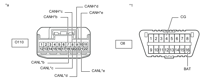
*1 DLC3 - - *a Front view of wire harness connector
(to No. 8 CAN Junction Connector)
*b to Absorber Control ECU
(w/ AVS System)
*c Driving Support ECU Assembly
(w/ Pre-crash Safety System)
*d to No. 6 CAN Junction Connector *e to Network Gateway ECU - - Standard Resistance Tester Connection Condition Specified Condition Result Connected to O110-7 (CANH) - O8-4 (CG) Cable disconnected from negative (-) battery terminal 200 Ω or higher Below 200 Ω: CANH short to ground Absorber control ECU*1 O110-18 (CANL) - O8-4 (CG) Cable disconnected from negative (-) battery terminal 200 Ω or higher Below 200 Ω: CANL short to ground O110-8 (CANH) - O8-4 (CG) Cable disconnected from negative (-) battery terminal 200 Ω or higher Below 200 Ω: CANH short to ground Driving support ECU assembly*2 O110-19 (CANL) - O8-4 (CG) Cable disconnected from negative (-) battery terminal 200 Ω or higher Below 200 Ω: CANL short to ground O110-9 (CANH) - O8-4 (CG) Cable disconnected from negative (-) battery terminal 200 Ω or higher Below 200 Ω: CANH short to ground No. 6 CAN junction connector O110-20 (CANL) - O8-4 (CG) Cable disconnected from negative (-) battery terminal 200 Ω or higher Below 200 Ω: CANL short to ground O110-10 (CANH) - O8-4 (CG) Cable disconnected from negative (-) battery terminal 200 Ω or higher Below 200 Ω: CANH short to ground Network gateway ECU O110-21 (CANL) - O8-4 (CG) Cable disconnected from negative (-) battery terminal 200 Ω or higher Below 200 Ω: CANL short to ground O110-7 (CANH) - O8-16 (BAT) Cable disconnected from negative (-) battery terminal 6 kΩ or higher Below 6 kΩ: CANH +B short Absorber control ECU*1 O110-18 (CANL) - O8-16 (BAT) Cable disconnected from negative (-) battery terminal 6 kΩ or higher Below 6 kΩ: CANL +B short O110-8 (CANH) - O8-16 (BAT) Cable disconnected from negative (-) battery terminal 6 kΩ or higher Below 6 kΩ: CANH +B short Driving support ECU assembly*2 O110-19 (CANL) - O8-16 (BAT) Cable disconnected from negative (-) battery terminal 6 kΩ or higher Below 6 kΩ: CANL +B short O110-9 (CANH) - O8-16 (BAT) Cable disconnected from negative (-) battery terminal 6 kΩ or higher Below 6 kΩ: CANH +B short No. 6 CAN junction connector O110-20 (CANL) - O8-16 (BAT) Cable disconnected from negative (-) battery terminal 6 kΩ or higher Below 6 kΩ: CANL +B short O110-10 (CANH) - O8-16 (BAT) Cable disconnected from negative (-) battery terminal 6 kΩ or higher Below 6 kΩ: CANH +B short Network gateway ECU O110-21 (CANL) - O8-16 (BAT) Cable disconnected from negative (-) battery terminal 6 kΩ or higher Below 6 kΩ: CANL +B short
-
*1: w/ AVS System
-
*2: w/ Pre-crash Safety System
Tech Tips
-
It is only necessary to perform the inspection in the above table for the result (short circuit) that was obtained in the Check Sub Bus inspection.
-
Find the necessary inspection from the Result column that matches the result in the Result column from the Check Sub Bus inspection.
Result Result Proceed to OK A NG (Network gateway ECU main line) B NG (ECU or sensor branch line) C NG (No. 6 CAN junction connector main line) D -
A
REPLACE NO. 8 CAN JUNCTION CONNECTOR
C
GO TO STEP 44 Click here
D
CHECK FOR SHORT IN SUB BUS LINE (NO. 6 CAN JUNCTION CONNECTOR) Click here
B
-
-
CHECK FOR SHORT IN SUB BUS LINE (NETWORK GATEWAY ECU)
-
Reconnect the O110 No. 8 CAN junction connector.
-
*a Front view of wire harness connector
(to Network Gateway ECU)
Disconnect the O46 network gateway ECU connector.
-
Measure the resistance according to the value(s) in the table below.
Standard Resistance Tester Connection Condition Specified Condition Result O46-13 (CA2H) - O46-4 (GND) Cable disconnected from negative (-) battery terminal 200 Ω or higher Below 200 Ω: CANH short to ground O46-12 (CA2L) - O46-4 (GND) Cable disconnected from negative (-) battery terminal 200 Ω or higher Below 200 Ω: CANL short to ground O46-13 (CA2H) - O46-2 (BATT) Cable disconnected from negative (-) battery terminal 6 kΩ or higher Below 6 kΩ: CANH +B short O46-12 (CA2L) - O46-2 (BATT) Cable disconnected from negative (-) battery terminal 6 kΩ or higher Below 6 kΩ: CANL +B short Tech Tips
-
It is only necessary to perform the inspection in the above table for the result (short circuit) that was obtained in the Check Sub Bus inspection.
-
Find the necessary inspection from the Result column that matches the result in the Result column from the Check Sub Bus inspection.
Result Result OK NG -
OK
REPLACE NETWORK GATEWAY ECU Click here
NG
REPAIR OR REPLACE CAN MAIN BUS LINE OR CONNECTOR (NETWORK GATEWAY ECU - NO. 8 CAN JUNCTION CONNECTOR)
-
-
CHECK FOR SHORT IN SUB BUS LINE (NO. 6 CAN JUNCTION CONNECTOR)
-
Reconnect the O110 No. 8 CAN junction connector.
-
Disconnect the O107 No. 6 CAN junction connector.
-
Measure the resistance according to the value(s) in the table below.
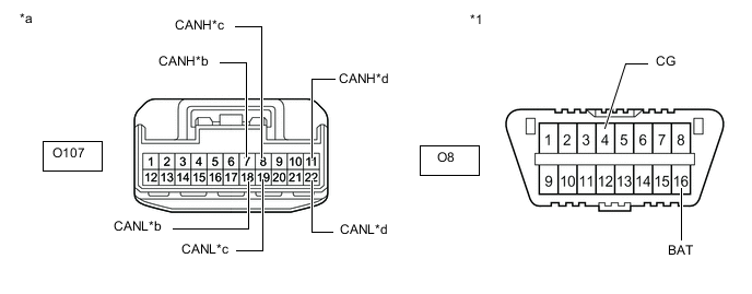
*1 DLC3 - - *a Front view of wire harness connector
(to No. 6 CAN Junction Connector)
*b to No. 8 CAN Junction Connector *c to No. 11 CAN Junction Connector *d to Clearance Warning ECU Assembly
(w/ LEXUS Parking Assist-sensor System)
Standard Resistance Tester Connection Condition Specified Condition Result Connected to O107-7 (CANH) - O8-4 (CG) Cable disconnected from negative (-) battery terminal 200 Ω or higher Below 200 Ω: CANH short to ground No. 8 CAN junction connector O107-18 (CANL) - O8-4 (CG) Cable disconnected from negative (-) battery terminal 200 Ω or higher Below 200 Ω: CANL short to ground O107-8 (CANH) - O8-4 (CG) Cable disconnected from negative (-) battery terminal 200 Ω or higher Below 200 Ω: CANH short to ground No. 11 CAN junction connector O107-19 (CANL) - O8-4 (CG) Cable disconnected from negative (-) battery terminal 200 Ω or higher Below 200 Ω: CANL short to ground O107-11 (CANH) - O8-4 (CG) Cable disconnected from negative (-) battery terminal 200 Ω or higher Below 200 Ω: CANH short to ground Clearance warning ECU assembly* O107-22 (CANL) - O8-4 (CG) Cable disconnected from negative (-) battery terminal 200 Ω or higher Below 200 Ω: CANL short to ground O107-7 (CANH) - O8-16 (BAT) Cable disconnected from negative (-) battery terminal 6 kΩ or higher Below 6 kΩ: CANH +B short No. 8 CAN junction connector O107-18 (CANL) - O8-16 (BAT) Cable disconnected from negative (-) battery terminal 6 kΩ or higher Below 6 kΩ: CANL +B short O107-8 (CANH) - O8-16 (BAT) Cable disconnected from negative (-) battery terminal 6 kΩ or higher Below 6 kΩ: CANH +B short No. 11 CAN junction connector O107-19 (CANL) - O8-16 (BAT) Cable disconnected from negative (-) battery terminal 6 kΩ or higher Below 6 kΩ: CANL +B short O107-11 (CANH) - O8-16 (BAT) Cable disconnected from negative (-) battery terminal 6 kΩ or higher Below 6 kΩ: CANH +B short Clearance warning ECU assembly* O107-22 (CANL) - O8-16 (BAT) Cable disconnected from negative (-) battery terminal 6 kΩ or higher Below 6 kΩ: CANL +B short
-
*: w/ LEXUS Parking Assist-sensor System
Tech Tips
-
It is only necessary to perform the inspection in the above table for the result (short circuit) that was obtained in the Check Sub Bus inspection.
-
Find the necessary inspection from the Result column that matches the result in the Result column from the Check Sub Bus inspection.
Result Result Proceed to OK A NG (ECU or sensor branch line) B NG (No. 8 CAN junction connector main line) C NG (No. 11 CAN junction connector main line) D -
A
REPLACE NO. 6 CAN JUNCTION CONNECTOR
B
GO TO STEP 44 Click here
C
REPAIR OR REPLACE CAN MAIN BUS LINE OR CONNECTOR (NO. 6 CAN JUNCTION CONNECTOR - NO. 8 CAN JUNCTION CONNECTOR)
D
-
-
CHECK FOR SHORT IN SUB BUS LINE (NO. 11 CAN JUNCTION CONNECTOR)
-
Reconnect the O107 No. 6 CAN junction connector.
-
Disconnect the W13 No. 11 CAN junction connector.
-
Measure the resistance according to the value(s) in the table below.
*1 DLC3 - - *a Front view of wire harness connector
(to No. 11 CAN Junction Connector)
*b to No. 6 CAN Junction Connector *c to No. 9 CAN Junction Connector *d to Lane Departure Warning Camera
(w/ Lane Departure Alert System)
Standard Resistance Tester Connection Condition Specified Condition Result Connected to W13-1 (CANH) - O8-4 (CG) Cable disconnected from negative (-) battery terminal 200 Ω or higher Below 200 Ω: CANH short to ground No. 6 CAN junction connector W13-7 (CANL) - O8-4 (CG) Cable disconnected from negative (-) battery terminal 200 Ω or higher Below 200 Ω: CANL short to ground W13-2 (CANH) - O8-4 (CG) Cable disconnected from negative (-) battery terminal 200 Ω or higher Below 200 Ω: CANH short to ground No. 9 CAN junction connector W13-8 (CANL) - O8-4 (CG) Cable disconnected from negative (-) battery terminal 200 Ω or higher Below 200 Ω: CANL short to ground W13-3 (CANH) - O8-4 (CG) Cable disconnected from negative (-) battery terminal 200 Ω or higher Below 200 Ω: CANH short to ground Lane departure warning camera* W13-9 (CANL) - O8-4 (CG) Cable disconnected from negative (-) battery terminal 200 Ω or higher Below 200 Ω: CANL short to ground W13-1 (CANH) - O8-16 (BAT) Cable disconnected from negative (-) battery terminal 6 kΩ or higher Below 6 kΩ: CANH +B short No. 6 CAN junction connector W13-7 (CANL) - O8-16 (BAT) Cable disconnected from negative (-) battery terminal 6 kΩ or higher Below 6 kΩ: CANL +B short W13-2 (CANH) - O8-16 (BAT) Cable disconnected from negative (-) battery terminal 6 kΩ or higher Below 6 kΩ: CANH +B short No. 9 CAN junction connector W13-8 (CANL) - O8-16 (BAT) Cable disconnected from negative (-) battery terminal 6 kΩ or higher Below 6 kΩ: CANL +B short W13-3 (CANH) - O8-16 (BAT) Cable disconnected from negative (-) battery terminal 6 kΩ or higher Below 6 kΩ: CANH +B short Lane departure warning camera* W13-9 (CANL) - O8-16 (BAT) Cable disconnected from negative (-) battery terminal 6 kΩ or higher Below 6 kΩ: CANL +B short
-
*: w/ Lane Departure Alert System
Tech Tips
-
It is only necessary to perform the inspection in the above table for the result (short circuit) that was obtained in the Check Sub Bus inspection.
-
Find the necessary inspection from the Result column that matches the result in the Result column from the Check Sub Bus inspection.
Result Result Proceed to OK A NG (ECU or sensor branch line) B NG (No. 6 CAN junction connector main line) C NG (No. 9 CAN junction connector main line) D -
A
REPLACE NO. 11 CAN JUNCTION CONNECTOR
B
GO TO STEP 44 Click here
C
REPAIR OR REPLACE CAN MAIN BUS LINE OR CONNECTOR (NO. 6 CAN JUNCTION CONNECTOR - NO. 11 CAN JUNCTION CONNECTOR)
D
-
-
CHECK FOR SHORT IN SUB BUS LINE (NO. 9 CAN JUNCTION CONNECTOR)
-
Reconnect the W13 No. 11 CAN junction connector.
-
Disconnect the U53 No. 9 CAN junction connector.
-
Measure the resistance according to the value(s) in the table below.
*1 DLC3 - - *a Front view of wire harness connector
(to No. 9 CAN Junction Connector)
*b to No. 11 CAN Junction Connector *c to No. 2 CAN Junction Terminal *d to Blind Spot Monitor Sensor LH
(w/ Blind Spot Monitor System)
Standard Resistance Tester Connection Condition Specified Condition Result Connected to U53-1 (CANH) - O8-4 (CG) Cable disconnected from negative (-) battery terminal 200 Ω or higher Below 200 Ω: CANH short to ground No. 11 CAN junction connector U53-12 (CANL) - O8-4 (CG) Cable disconnected from negative (-) battery terminal 200 Ω or higher Below 200 Ω: CANL short to ground U53-2 (CANH) - O8-4 (CG) Cable disconnected from negative (-) battery terminal 200 Ω or higher Below 200 Ω: CANH short to ground No. 2 CAN junction terminal U53-13 (CANL) - O8-4 (CG) Cable disconnected from negative (-) battery terminal 200 Ω or higher Below 200 Ω: CANL short to ground U53-3 (CANH) - O8-4 (CG) Cable disconnected from negative (-) battery terminal 200 Ω or higher Below 200 Ω: CANH short to ground Blind spot monitor sensor LH* U53-14 (CANL) - O8-4 (CG) Cable disconnected from negative (-) battery terminal 200 Ω or higher Below 200 Ω: CANL short to ground U53-1 (CANH) - O8-16 (BAT) Cable disconnected from negative (-) battery terminal 6 kΩ or higher Below 6 kΩ: CANH +B short No. 11 CAN junction connector U53-12 (CANL) - O8-16 (BAT) Cable disconnected from negative (-) battery terminal 6 kΩ or higher Below 6 kΩ: CANL +B short U53-2 (CANH) - O8-16 (BAT) Cable disconnected from negative (-) battery terminal 6 kΩ or higher Below 6 kΩ: CANH +B short No. 2 CAN junction terminal U53-13 (CANL) - O8-16 (BAT) Cable disconnected from negative (-) battery terminal 6 kΩ or higher Below 6 kΩ: CANL +B short U53-3 (CANH) - O8-16 (BAT) Cable disconnected from negative (-) battery terminal 6 kΩ or higher Below 6 kΩ: CANH +B short Blind spot monitor sensor LH* U53-14 (CANL) - O8-16 (BAT) Cable disconnected from negative (-) battery terminal 6 kΩ or higher Below 6 kΩ: CANL +B short
-
*: w/ Blind Spot Monitor System
Tech Tips
-
It is only necessary to perform the inspection in the above table for the result (short circuit) that was obtained in the Check Sub Bus inspection.
-
Find the necessary inspection from the Result column that matches the result in the Result column from the Check Sub Bus inspection.
Result Result Proceed to OK A NG (No. 11 CAN junction connector main line) B NG (ECU or sensor branch line) C NG (No. 2 CAN junction terminal main line) D -
A
REPLACE NO. 9 CAN JUNCTION CONNECTOR
B
REPAIR OR REPLACE CAN MAIN BUS LINE OR CONNECTOR (NO. 9 CAN JUNCTION CONNECTOR - NO. 11 CAN JUNCTION CONNECTOR)
D
CHECK FOR SHORT IN SUB BUS LINE (NO. 2 CAN JUNCTION TERMINAL) Click here
C
-
-
CHECK FOR SHORT IN SUB BUS LINE (ECU, SENSOR)
-
Reconnect all wire harness connectors.
-
Disconnect the connector that includes terminals CANH and CANL from the ECU or sensor to which the bus line shorted to +B or shorted to GND is connected.
-
*a Component with harness connected
(Network Gateway ECU)
Measure the resistance according to the value(s) in the table below.
Standard Resistance Tester Connection Condition Specified Condition Result O46-13 (CA2H) - O46-4 (GND) Cable disconnected from negative (-) battery terminal 200 Ω or higher Below 200 Ω: CANH short to ground O46-12 (CA2L) - O46-4 (GND) Cable disconnected from negative (-) battery terminal 200 Ω or higher Below 200 Ω: CANL short to ground O46-13 (CA2H) - O46-2 (BATT) Cable disconnected from negative (-) battery terminal 6 kΩ or higher Below 6 kΩ: CANH +B short O46-12 (CA2L) - O46-2 (BATT) Cable disconnected from negative (-) battery terminal 6 kΩ or higher Below 6 kΩ: CANL +B short Tech Tips
-
It is only necessary to perform the inspection in the above table for the result (short circuit) that was obtained in the Check Sub Bus inspection.
-
If the resistance becomes normal when the connector is disconnected from the ECU or sensor, there may be a short in the ECU or sensor.
-
Find the necessary inspection from the Result column that matches the result in the Result column from the Check Sub Bus inspection.
Result Result OK NG -
OK
REPLACE CORRESPONDING ECU OR SENSOR
NG
REPAIR OR REPLACE CORRESPONDING ECU OR SENSOR BRANCH LINE OR CONNECTOR
-
-
CHECK FOR SHORT IN SUB BUS LINE (NO. 2 CAN JUNCTION TERMINAL)
-
Reconnect the U53 No. 9 CAN junction connector.
-
*1 DLC3 *a Front view of wire harness connector
(to No. 2 CAN Junction Terminal)
Disconnect the O102 No. 2 CAN junction terminal connector.
-
Measure the resistance according to the value(s) in the table below.
Standard Resistance Tester Connection Condition Specified Condition Result O102-3 (CANH) - O8-4 (CG) Cable disconnected from negative (-) battery terminal 200 Ω or higher Below 200 Ω: CANH short to ground O102-2 (CANL) - O8-4 (CG) Cable disconnected from negative (-) battery terminal 200 Ω or higher Below 200 Ω: CANL short to ground O102-3 (CANH) - O8-16 (BAT) Cable disconnected from negative (-) battery terminal 6 kΩ or higher Below 6 kΩ: CANH +B short O102-2 (CANL) - O8-16 (BAT) Cable disconnected from negative (-) battery terminal 6 kΩ or higher Below 6 kΩ: CANL +B short Tech Tips
-
It is only necessary to perform the inspection in the above table for the result (short circuit) that was obtained in the Check Sub Bus inspection.
-
Find the necessary inspection from the Result column that matches the result in the Result column from the Check Sub Bus inspection.
Result Result OK NG -
OK
REPLACE NO. 2 CAN JUNCTION TERMINAL
NG
REPAIR OR REPLACE CAN MAIN BUS LINE OR CONNECTOR (NO. 9 CAN JUNCTION CONNECTOR - NO. 2 CAN JUNCTION TERMINAL)
-