CAN COMMUNICATION SYSTEM TERMINALS OF ECU
Note
-
After turning the engine switch off, waiting time may be required before disconnecting the cable from the negative (-) battery terminal. Therefore, make sure to read the disconnecting the cable from the negative (-) battery terminal notices before proceeding with work.
-
Turn the engine switch off before measuring the resistances between CAN main bus lines and between CAN branch lines.
-
Turn the engine switch off before inspecting CAN bus lines for a short to ground.
-
Before measuring the resistance of the CAN bus, turn the engine switch off and leave the vehicle for 1 minute or more without operating the key or any switches, or opening or closing the doors. After that, disconnect the cable from the negative (-) battery terminal and leave the vehicle for 1 minute or more before measuring the resistance.
-
This section describes the standard values for all CAN related components.
Tech Tips
-
Operating the engine switch, any other switches or a door triggers related ECU and sensor communication on the CAN. This communication will cause the resistance value to change.
-
Even after DTCs are cleared, if a DTC is stored again after driving the vehicle for a while, the malfunction may be occurring due to vibration of the vehicle. In such a case, wiggling the ECUs or wire harness while performing the inspection below may help determine the cause of the malfunction.
-
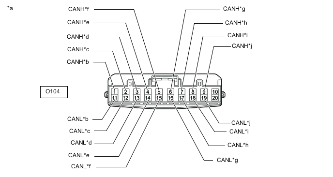
NO. 1 CAN JUNCTION CONNECTOR (for LHD)
-
Check the No. 1 CAN junction connector.
-
Connection diagram
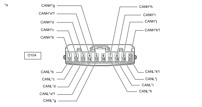
*a Front view of wire harness connector
(to No. 1 CAN Junction Connector)
*b to No. 2 CAN Junction Connector
(for V Bus)
*c to Combination Meter Assembly
(for V Bus)
*d to Radio Receiver Assembly
(for V Bus)
*e to Network Gateway ECU
(w/ Network Gateway ECU)
(for V Bus)
*f to Option Connector (Bus Buffer ECU)
(w/o Network Gateway ECU)
(for V Bus)
*g to Air Conditioning Amplifier Assembly
(for V Bus)
*h to Certification ECU (Smart Key ECU Assembly)
(for V Bus)
*i to Stereo Component Equalizer Assembly
(w/ ASC System)
(for V Bus)
*j to Power Steering ECU Assembly
(for V Bus)
*k to Front Steering Control ECU
(w/ VGRS System)
(for V Bus)
*l to Engine Stop and Start ECU
(w/ Stop and Start System)
(for V Bus)
-
Check the connection diagram of the components which are connected to the No. 1 CAN junction connector.
Terminal No. (Symbol) Wiring Color Connected to O104-1 (CANH) L No. 2 CAN junction connector
(for V bus)
O104-11 (CANL) B O104-2 (CANH) LG Combination meter assembly
(for V bus)
O104-12 (CANL) B O104-3 (CANH) R Radio receiver assembly
(for V bus)
O104-13 (CANL) B O104-4 (CANH) BE Network gateway ECU*1
(for V bus)
O104-14 (CANL) B O104-4 (CANH) BE Option connector (bus buffer ECU)*2
(for V bus)
O104-14 (CANL) B O104-5 (CANH) P Air conditioning amplifier assembly
(for V bus)
O104-15 (CANL) B O104-7 (CANH) W Certification ECU (smart key ECU assembly)
(for V bus)
O104-17 (CANL) B O104-8 (CANH) V Stereo component equalizer assembly*3
(for V bus)
O104-18 (CANL) B O104-9 (CANH) G Power steering ECU assembly
(for V bus)
O104-19 (CANL) B O104-10 (CANH) GR Front steering control ECU*4
(for V bus)
O104-20 (CANL) B O104-10 (CANH) GR Engine stop and start ECU*5
(for V bus)
O104-20 (CANL) B
-
*1: w/ Network Gateway ECU
-
*2: w/o Network Gateway ECU
-
*3: w/ ASC System
-
*4: w/ VGRS System
-
*5: w/ Stop and Start System
-
-
-
-
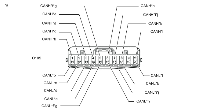
NO. 2 CAN JUNCTION CONNECTOR (for LHD)
-
Check the No. 2 CAN junction connector.
-
Connection diagram
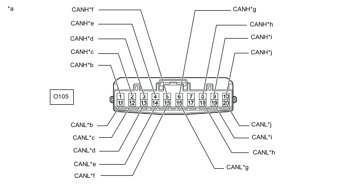
*a Front view of wire harness connector
(to No. 2 CAN Junction Connector)
*b to No. 1 CAN Junction Connector
(for V Bus)
*c to Main Body ECU (Multiplex Network Body ECU)
(for V Bus)
*d to ECM
(for V Bus)
*e to Headlight Leveling ECU Assembly
(for Single Beam Headlight)
(for V Bus)
*f to Airbag Sensor Assembly
(for V Bus)
*g to Yaw Rate Sensor
(for V Bus)
*h to DLC3
(for V Bus)
*i to Steering Sensor
(for V Bus)
*j to Skid Control ECU (Brake Actuator Assembly)
(for V Bus)
-
Check the connection diagram of the components which are connected to the No. 2 CAN junction connector.
Terminal No. (Symbol) Wiring Color Connected to O105-1 (CANH) L No. 1 CAN junction connector
(for V bus)
O105-11 (CANL) B O105-2 (CANH) Y Main body ECU (multiplex network body ECU)
(for V bus)
O105-12 (CANL) B O105-3 (CANH) R ECM
(for V bus)
O105-13 (CANL) B O105-4 (CANH) LG Headlight leveling ECU assembly*
(for V bus)
O105-14 (CANL) B O105-5 (CANH) BE Airbag sensor assembly
(for V bus)
O105-15 (CANL) B O105-6 (CANH) G Yaw rate sensor
(for V bus)
O105-16 (CANL) B O105-8 (CANH) W DLC3
(for V bus)
O105-18 (CANL) B O105-9 (CANH) P Steering sensor
(for V bus)
O105-19 (CANL) B O105-10 (CANH) SB Skid control ECU (brake actuator assembly)
(for V bus)
O105-20 (CANL) B
-
*: for Single Beam Headlight
-
-
-
-
NO. 5 CAN JUNCTION CONNECTOR (for LHD with Network Gateway ECU, Seat Position Memory System, Power Tilt and Power Telescopic System, Triple Beam Headlight or Parking Assist Monitor System without Parallel Parking Assist Function)
-
Check the No. 5 CAN junction connector.
-
Connection diagram
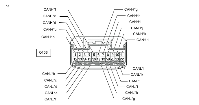
*a Front view of wire harness connector
(to No. 5 CAN Junction Connector)
*b to Multiplex Tilt and Telescopic ECU
(w/ Power Tilt and Power Telescopic System)
(for Sub Bus 1)
*c to No. 9 CAN Junction Connector
(w/ Seat Position Memory System, Power Tilt and Power Telescopic System, Triple Beam Headlight or Parking Assist Monitor System without Parallel Parking Assist Function)
(for Sub Bus 1)
*d to Main Body ECU (Multiplex Network Body ECU)
(w/ Seat Position Memory System, Power Tilt and Power Telescopic System, Triple Beam Headlight or Parking Assist Monitor System without Parallel Parking Assist Function)
(for Sub Bus 1)
*e to Outer Mirror Control ECU Assembly (for Driver Side)
(w/ Seat Position Memory System)
(for Sub Bus 1)
*f to Headlight Light Control ECU Sub-assembly LH
(for Triple Beam Headlight)
(for Sub Bus 1)
*g to Position Control ECU and Switch Assembly LH
(w/ Seat Position Memory System)
(for Sub Bus 1)
*h to No. 7 CAN Junction Connector
(w/ Network Gateway ECU)
(for Sub Bus 2 (w/o VGRS System))
(for Sub Bus 18 (w/ VGRS System))
*i to No. 11 CAN Junction Connector
(w/ Network Gateway ECU)
(for Sub Bus 2 (w/o VGRS System))
(for Sub Bus 18 (w/ VGRS System))
*j to Option Connector (Bus Buffer ECU)
(w/ Network Gateway ECU and Option Connector)
(for Sub Bus 2 (w/o VGRS System))
(for Sub Bus 18 (w/ VGRS System))
*k to Driving Support ECU Assembly
(w/ Pre-crash Safety System)
(for Sub Bus 2 (w/o VGRS System))
(for Sub Bus 18 (w/ VGRS System))
*l to Clearance Warning ECU Assembly
(w/ LEXUS Parking Assist-sensor System)
(for Sub Bus 2 (w/o VGRS System))
(for Sub Bus 18 (w/ VGRS System))
-
Check the connection diagram of the components which are connected to the No. 5 CAN junction connector.
Terminal No. (Symbol) Wiring Color Connected to O106-1 (CANH) BE Multiplex tilt and telescopic ECU*1
(for Sub bus 1)
O106-12 (CANL) B O106-2 (CANH) L No. 9 CAN junction connector*2
(for Sub bus 1)
O106-13 (CANL) B O106-3 (CANH) P Main body ECU (multiplex network body ECU)*2
(for Sub bus 1)
O106-14 (CANL) B O106-4 (CANH) W Outer mirror control ECU assembly (for driver side)*3
(for Sub bus 1)
O106-15 (CANL) B O106-5 (CANH) V Headlight light control ECU sub-assembly LH*4
(for Sub bus 1)
O106-16 (CANL) B O106-6 (CANH) R Position control ECU and switch assembly LH*3
(for Sub bus 1)
O106-17 (CANL) B O106-7 (CANH) Y No. 7 CAN junction connector*5
(for Sub bus 2*6 or sub bus 18*7)
O106-18 (CANL) B O106-8 (CANH) LG No. 11 CAN junction connector*5
(for Sub bus 2*6 or sub bus 18*7)
O106-19 (CANL) B O106-9 (CANH) GR Option connector (bus buffer ECU)*10
(for Sub bus 2*6 or sub bus 18*7)
O106-20 (CANL) B O106-10 (CANH) G Driving support ECU assembly*8
(for Sub bus 2*6 or sub bus 18*7)
O106-21 (CANL) B O106-11 (CANH) SB Clearance warning ECU assembly*9
(for Sub bus 2*6 or sub bus 18*7)
O106-22 (CANL) B
-
*1: w/ Power Tilt and Power Telescopic System
-
*2: w/ Seat Position Memory System, Power Tilt and Power Telescopic System, Triple Beam Headlight or Parking Assist Monitor System without Parallel Parking Assist Function
-
*3: w/ Seat Position Memory System
-
*4: for Triple Beam Headlight
-
*5: w/ Network Gateway ECU
-
*6: w/o VGRS System
-
*7: w/ VGRS System
-
*8: w/ Pre-crash Safety System
-
*9: w/ LEXUS Parking Assist-sensor System
-
*10: w/ Network Gateway ECU and Option Connector
-
-
-
-
NO. 7 CAN JUNCTION CONNECTOR (for LHD with Network Gateway ECU)
-
Check the No. 7 CAN junction connector.
-
Connection diagram
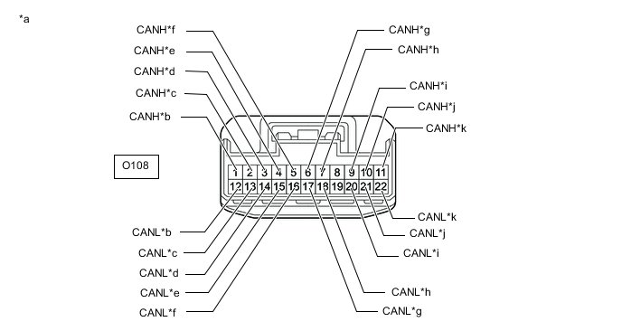
*a Front view of wire harness connector
(to No. 7 CAN Junction Connector)
*b to Front Steering Control ECU
(w/ VGRS System)
(for Sub Bus 19)
*c to Power Steering ECU Assembly
(w/ VGRS System)
(for Sub Bus 19)
*d to Skid Control ECU (Brake Actuator Assembly
(w/ VGRS System)
(for Sub Bus 19)
*e to No. 9 CAN Junction Connector
(w/ VGRS System)
(for Sub Bus 19)
*f to Absorber Control ECU
(w/ AVS System and VGRS System)
(for Sub Bus 19)
*g to Network Gateway ECU
(w/ VGRS System)
(for Sub Bus 19)
*h to Absorber Control ECU
(w/ AVS System)
(for Sub Bus 2 (w/o VGRS System))
(for Sub Bus 18 (w/ VGRS System))
*i to No. 5 CAN Junction Connector
(for Sub Bus 2 (w/o VGRS System))
(for Sub Bus 18 (w/ VGRS System))
*j to Network Gateway ECU
(for Sub Bus 2 (w/o VGRS System))
(for Sub Bus 18 (w/ VGRS System))
*k to Telematics Transceiver
(w/ Telematics Transceiver)
(for Sub Bus 2 (w/o VGRS System))
(for Sub Bus 18 (w/ VGRS System))
- - -
Check the connection diagram of the components which are connected to the No. 7 CAN junction connector.
Terminal No. (Symbol) Wiring Color Connected to O108-1 (CANH) R Front steering control ECU*1
(for Sub bus 19)
O108-12 (CANL) B O108-2 (CANH) W Power steering ECU assembly*1
(for Sub bus 19)
O108-13 (CANL) B O108-3 (CANH) LG Skid control ECU (brake actuator assembly)*1
(for Sub bus 19)
O108-14 (CANL) B O108-4 (CANH) P No. 9 CAN junction connector*1
(for Sub bus 19)
O108-15 (CANL) B O108-5 (CANH) G Absorber control ECU*2
(for Sub bus 19)
O108-16 (CANL) B O108-6 (CANH) L Network gateway ECU*1
(for Sub bus 19)
O108-17 (CANL) B O108-7 (CANH) SB Absorber control ECU*3
(for Sub bus 2*4 or sub bus 18*1)
O108-18 (CANL) B O108-9 (CANH) Y No. 5 CAN junction connector
(for Sub bus 2*4 or sub bus 18*1)
O108-20 (CANL) B O108-10 (CANH) GR Network gateway ECU
(for Sub bus 2*4 or sub bus 18*1)
O108-21 (CANL) B O108-11 (CANH) BE Telematics Transceiver*5
(for Sub bus 2*4 or sub bus 18*1)
O108-22 (CANL) B
-
*1: w/ VGRS System
-
*2: w/ AVS System and VGRS System
-
*3: w/ AVS System
-
*4: w/o VGRS System
-
*5: w/ Telematics Transceiver
-
-
-
-
NO. 9 CAN JUNCTION CONNECTOR (for LHD with Network Gateway ECU, Seat Position Memory System, Power Tilt and Power Telescopic System, Triple Beam Headlight or Parking Assist Monitor System without Parallel Parking Assist Function)
-
Check the No. 9 CAN junction connector.
-
Connection diagram
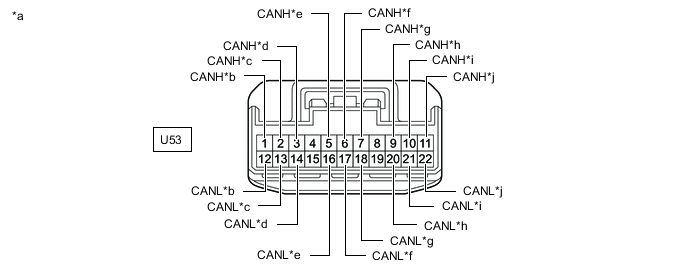
*a Front view of wire harness connector
(to No. 9 CAN Junction Connector)
*b to No. 11 CAN Junction Connector
(w/ Network Gateway ECU)
(for Sub Bus 2 (w/o VGRS System))
(for Sub Bus 18 (w/ VGRS System))
*c to No. 2 CAN Junction Terminal
(w/ Network Gateway ECU)
(for Sub Bus 2 (w/o VGRS System))
(for Sub Bus 18 (w/ VGRS System))
*d to Blind Spot Monitor Sensor LH
(w/ Blind Spot Monitor System)
(for Sub Bus 2 (w/o VGRS System))
(for Sub Bus 18 (w/ VGRS System))
*e to No. 7 CAN Junction Connector
(w/ VGRS System)
(for Sub Bus 19)
*f to No. 3 CAN Junction Terminal
(w/ VGRS System)
(for Sub Bus 19)
*g to Rear Steering Control ECU
(w/ VGRS System)
(for Sub Bus 19)
*h to No. 10 CAN Junction Connector
(w/ Seat Position Memory System, Power Tilt and Power Telescopic System, Triple Beam Headlight or Parking Assist Monitor System without Parallel Parking Assist Function)
(for Sub Bus 1)
*i to No. 5 CAN Junction Connector
(w/ Seat Position Memory System, Power Tilt and Power Telescopic System, Triple Beam Headlight or Parking Assist Monitor System without Parallel Parking Assist Function)
(for Sub Bus 1)
*j to Rear Television Camera Assembly
(w/ Parking Assist Monitor System without Parallel Parking Assist Function)
(for Sub Bus 1)
-
Check the connection diagram of the components which are connected to the No. 9 CAN junction connector.
Terminal No. (Symbol) Wiring Color Connected to U53-1 (CANH) BE No. 11 CAN junction connector*1
(for Sub bus 2*2 or sub bus 18*3)
U53-12 (CANL) B U53-2 (CANH) V No. 2 CAN junction terminal*1
(for Sub bus 2*2 or sub bus 18*3)
U53-13 (CANL) B U53-3 (CANH) R Blind spot monitor sensor LH*4
(for Sub bus 2*2 or sub bus 18*3)
U53-14 (CANL) B U53-5 (CANH) P No. 7 CAN junction connector*3
(for Sub bus 19)
U53-16 (CANL) B U53-6 (CANH) V No. 3 CAN junction terminal*3
(for Sub bus 19)
U53-17 (CANL) B U53-7 (CANH) G Rear steering control ECU*3
(for Sub bus 19)
U53-18 (CANL) B U53-9 (CANH) LG No. 10 CAN junction connector*5
(for Sub bus 1)
U53-20 (CANL) B U53-10 (CANH) L No. 5 CAN junction connector*5
(for Sub bus 1)
U53-21 (CANL) B U53-11 (CANH) W Rear television camera assembly*6
(for Sub bus 1)
U53-22 (CANL) B
-
*1: w/ Network Gateway ECU
-
*2: w/o VGRS System
-
*3: w/ VGRS System
-
*4: w/ Blind Spot Monitor System
-
*5: w/ Seat Position Memory System, Power Tilt and Power Telescopic System, Triple Beam Headlight or Parking Assist Monitor System without Parallel Parking Assist Function
-
*6: w/ Parking Assist Monitor System without Parallel Parking Assist Function
-
-
-
-
NO. 10 CAN JUNCTION CONNECTOR (for LHD with Seat Position Memory System, Power Tilt and Power Telescopic System, Triple Beam Headlight or Parking Assist Monitor System without Parallel Parking Assist Function)
-
Check the No. 10 CAN junction connector.
-
Connection diagram
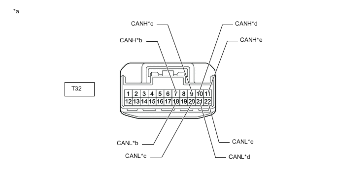
*a Front view of wire harness connector
(to No. 10 CAN Junction Connector)
*b to No. 9 CAN Junction Connector
(for Sub Bus 1)
*c to Position Control ECU and Switch Assembly RH
(w/ Seat Position Memory System)
(for Sub Bus 1)
*d to Outer Mirror Control ECU Assembly(for Front Passenger Side)
(w/ Seat Position Memory System)
(for Sub Bus 1)
*e to No. 1 CAN Junction Terminal
(for Sub Bus 1)
- - -
Check the connection diagram of the components which are connected to the No. 10 CAN junction connector.
Terminal No. (Symbol) Wiring Color Connected to T32-7 (CANH) LG No. 9 CAN junction connector
(for Sub bus 1)
T32-18 (CANL) B T32-9 (CANH) R Position control ECU and switch assembly RH*
(for Sub bus 1)
T32-20 (CANL) B T32-10 (CANH) W Outer mirror control ECU assembly (for front passenger side)*
(for Sub bus 1)
T32-21 (CANL) B T32-11 (CANH) P No. 1 CAN junction terminal
(for Sub bus 1)
T32-22 (CANL) B
-
*: w/ Seat Position Memory System
-
-
-
-
NO. 11 CAN JUNCTION CONNECTOR (for LHD with Network Gateway ECU)
-
Check the No. 11 CAN junction connector.
-
Connection diagram

*a Front view of wire harness connector
(to No. 11 CAN Junction Connector)
*b to No. 5 CAN Junction Connector
(for Sub Bus 2 (w/o VGRS System))
(for Sub Bus 18 (w/ VGRS System))
*c to No. 9 CAN Junction Connector
(for Sub Bus 2 (w/o VGRS System))
(for Sub Bus 18 (w/ VGRS System))
*d to Lane Departure Warning Camera
(w/ Lane Departure Alert System)
(for Sub Bus 2 (w/o VGRS System))
(for Sub Bus 18 (w/ VGRS System))
-
Check the connection diagram of the components which are connected to the No. 11 CAN junction connector.
Terminal No. (Symbol) Wiring Color Connected to W13-1 (CANH) LG No. 5 CAN junction connector
(for Sub bus 2*1 or sub bus 18*2)
W13-7 (CANL) B W13-2 (CANH) BE No. 9 CAN junction connector
(for Sub bus 2*1 or sub bus 18*2)
W13-8 (CANL) B W13-3 (CANH) R Lane departure warning camera*3
(for Sub bus 2*1 or sub bus 18*2)
W13-9 (CANL) B
-
*1: w/o VGRS System
-
*2: w/ VGRS System
-
*3: w/ Lane Departure Alert System
-
-
-
-
NO. 1 CAN JUNCTION CONNECTOR (for RHD)
-
Check the No. 1 CAN junction connector.
-
Connection diagram
*a Front view of wire harness connector
(to No. 1 CAN Junction Connector)
*b to No. 2 CAN Junction Connector
(for V Bus)
*c to Combination Meter Assembly
(for V Bus)
*d to Radio Receiver Assembly
(for V Bus)
*e to Airbag Sensor Assembly
(for V Bus)
*f to Yaw Rate Sensor
(for V Bus)
*g to Skid Control ECU (Brake Actuator Assembly)
(for V Bus)
*h to Steering Sensor
(for V Bus)
*i to DLC3
(for V Bus)
*j to Stereo Component Equalizer Assembly
(w/ ASC System)
(for V Bus)
-
Check the connection diagram of the components which are connected to the No. 1 CAN junction connector.
Terminal No. (Symbol) Wiring Color Connected to O104-1 (CANH) L No. 2 CAN junction connector
(for V bus)
O104-11 (CANL) B O104-2 (CANH) LG Combination meter assembly
(for V bus)
O104-12 (CANL) B O104-3 (CANH) R Radio receiver assembly
(for V bus)
O104-13 (CANL) B O104-4 (CANH) BE Airbag sensor assembly
(for V bus)
O104-14 (CANL) B O104-5 (CANH) G Yaw rate sensor
(for V bus)
O104-15 (CANL) B O104-6 (CANH) SB Skid control ECU (brake actuator assembly)
(for V bus)
O104-16 (CANL) B O104-7 (CANH) P Steering sensor
(for V bus)
O104-17 (CANL) B O104-8 (CANH) W DLC3
(for V bus)
O104-18 (CANL) B O104-9 (CANH) V Stereo component equalizer assembly*
(for V bus)
O104-19 (CANL) B
-
*: w/ ASC System
-
-
-
-
NO. 2 CAN JUNCTION CONNECTOR (for RHD)
-
Check the No. 2 CAN junction connector.
-
Connection diagram
*a Front view of wire harness connector
(to No. 2 CAN Junction Connector)
*b to No. 1 CAN Junction Connector
(for V Bus)
*c to Main Body ECU (Multiplex Network Body ECU)
(for V Bus)
*d to ECM
(for V Bus)
*e to Headlight Leveling ECU Assembly
(for Single Beam Headlight)
(for V Bus)
*f to Network Gateway ECU
(w/ Network Gateway ECU)
(for V Bus)
*g to Option Connector (Bus Buffer ECU)
(w/o Network Gateway ECU)
(for V Bus)
*h to Air Conditioning Amplifier Assembly
(for V Bus)
*i to Front Steering Control ECU
(w/ VGRS System)
(for V Bus)
*j to Engine Stop and Start ECU
(w/ Stop and Start System)
(for V Bus)
*k to Certification ECU (Smart Key ECU Assembly)
(for V Bus)
*l to Power Steering ECU Assembly
(for V Bus)
-
Check the connection diagram of the components which are connected to the No. 2 CAN junction connector.
Terminal No. (Symbol) Wiring Color Connected to O105-1 (CANH) L No. 1 CAN junction connector
(for V bus)
O105-11 (CANL) B O105-2 (CANH) Y Main body ECU (multiplex network body ECU)
(for V bus)
O105-12 (CANL) B O105-3 (CANH) R ECM
(for V bus)
O105-13 (CANL) B O105-4 (CANH) LG Headlight leveling ECU assembly*1
(for V bus)
O105-14 (CANL) B O105-5 (CANH) BE Network gateway ECU*2
(for V bus)
O105-15 (CANL) B O105-5 (CANH) BE Option connector (bus buffer ECU)*3
(for V bus)
O105-15 (CANL) B O105-6 (CANH) P Air conditioning amplifier assembly
(for V bus)
O105-16 (CANL) B O105-7 (CANH) GR Front steering control ECU*4
(for V bus)
O105-17 (CANL) B O105-7 (CANH) GR Engine stop and start ECU*5
(for V bus)
O105-17 (CANL) B O105-8 (CANH) W Certification ECU (smart key ECU assembly)
(for V bus)
O105-18 (CANL) B O105-10 (CANH) G Power steering ECU assembly
(for V bus)
O105-20 (CANL) B
-
*1: for Single Beam Headlight
-
*2: w/ Network Gateway ECU
-
*3: w/o Network Gateway ECU
-
*4: w/ VGRS System
-
*5: w/ Stop and Start System
-
-
-
-
NO. 6 CAN JUNCTION CONNECTOR (for RHD with Network Gateway ECU, Seat Position Memory System, Power Tilt and Power Telescopic System, Triple Beam Headlight or Parking Assist Monitor System without Parallel Parking Assist Function)
-
Check the No. 6 CAN junction connector.
-
Connection diagram
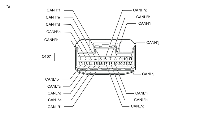
*a Front view of wire harness connector
(to No. 6 CAN Junction Connector)
*b to Multiplex Tilt and Telescopic ECU
(w/ Power Tilt and Power Telescopic System)
(for Sub Bus 1)
*c to No. 9 CAN Junction Connector
(w/ Seat Position Memory System, Power Tilt and Power Telescopic System, Triple Beam Headlight or Parking Assist Monitor System without Parallel Parking Assist Function)
(for Sub Bus 1)
*d to Main Body ECU (Multiplex Network Body ECU)
(w/ Seat Position Memory System, Power Tilt and Power Telescopic System, Triple Beam Headlight or Parking Assist Monitor System without Parallel Parking Assist Function)
(for Sub Bus 1)
*e to Outer Mirror Control ECU Assembly(for Front Passenger Side)
(w/ Seat Position Memory System)
(for Sub Bus 1)
*f to Headlight Light Control ECU Sub-assembly LH
(for Triple Beam Headlight)
(for Sub Bus 1)
*g to Position Control ECU and Switch Assembly LH
(w/ Seat Position Memory System)
(for Sub Bus 1)
*h to No. 8 CAN Junction Connector
(w/ Network Gateway ECU)
(for Sub Bus 2 (w/o VGRS System))
(for Sub Bus 18 (w/ VGRS System))
*i to No. 11 CAN Junction Connector
(w/ Network Gateway ECU)
(for Sub Bus 2 (w/o VGRS System))
(for Sub Bus 18 (w/ VGRS System))
*j to Clearance Warning ECU Assembly
(w/ LEXUS Parking Assist-sensor System)
(for Sub Bus 2 (w/o VGRS System))
(for Sub Bus 18 (w/ VGRS System))
-
Check the connection diagram of the components which are connected to the No. 6 CAN junction connector.
Terminal No. (Symbol) Wiring Color Connected to O107-1 (CANH) BE Multiplex tilt and telescopic ECU*1
(for Sub bus 1)
O107-12 (CANL) B O107-2 (CANH) L No. 9 CAN junction connector*2
(for Sub bus 1)
O107-13 (CANL) B O107-3 (CANH) P Main body ECU (multiplex network body ECU)*2
(for Sub bus 1)
O107-14 (CANL) B O107-4 (CANH) W Outer mirror control ECU assembly (for front passenger side)*3
(for Sub bus 1)
O107-15 (CANL) B O107-5 (CANH) V Headlight light control ECU sub-assembly LH*4
(for Sub bus 1)
O107-16 (CANL) B O107-6 (CANH) R Position control ECU and switch assembly LH*3
(for Sub bus 1)
O107-17 (CANL) B O107-7 (CANH) Y No. 8 CAN junction connector*5
(for Sub bus 2*6 or sub bus 18*7)
O107-18 (CANL) B O107-8 (CANH) LG No. 11 CAN junction connector*5
(for Sub bus 2*6 or sub bus 18*7)
O107-19 (CANL) B O107-11 (CANH) SB Clearance warning ECU assembly*8
(for Sub bus 2*6 or sub bus 18*7)
O107-22 (CANL) B
-
*1: w/ Power Tilt and Power Telescopic System
-
*2: w/ Seat Position Memory System, Power Tilt and Power Telescopic System, Triple Beam Headlight or Parking Assist Monitor System without Parallel Parking Assist Function
-
*3: w/ Seat Position Memory System
-
*4: for Triple Beam Headlight
-
*5: w/ Network Gateway ECU
-
*6: w/o VGRS System
-
*7: w/ VGRS System
-
*8: w/ LEXUS Parking Assist-sensor System
-
-
-
-
NO. 8 CAN JUNCTION CONNECTOR (for RHD with Network Gateway ECU)
-
Check the No. 8 CAN junction connector.
-
Connection diagram
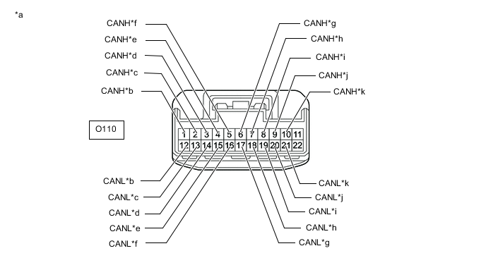
*a Front view of wire harness connector
(to No. 8 CAN Junction Connector)
*b to Front Steering Control ECU
(w/ VGRS System)
(for Sub Bus 19)
*c to Power Steering ECU Assembly
(w/ VGRS System)
(for Sub Bus 19)
*d to Skid Control ECU (Brake Actuator Assembly
(w/ VGRS System)
(for Sub Bus 19)
*e to No. 9 CAN Junction Connector
(w/ VGRS System)
(for Sub Bus 19)
*f to Absorber Control ECU
(w/ AVS System and VGRS System)
(for Sub Bus 19)
*g to Network Gateway ECU
(w/ VGRS System)
(for Sub Bus 19)
*h to Absorber Control ECU
(w/ AVS System)
(for Sub Bus 2 (w/o VGRS System))
(for Sub Bus 18 (w/ VGRS System))
*i to Driving Support ECU Assembly
(w/ Pre-crash Safety System)
(for Sub Bus 2 (w/o VGRS System))
(for Sub Bus 18 (w/ VGRS System))
*j to No. 6 CAN Junction Connector
(for Sub Bus 2 (w/o VGRS System))
(for Sub Bus 18 (w/ VGRS System))
*k to Network Gateway ECU
(for Sub Bus 2 (w/o VGRS System))
(for Sub Bus 18 (w/ VGRS System))
- - -
Check the connection diagram of the components which are connected to the No. 8 CAN junction connector.
Terminal No. (Symbol) Wiring Color Connected to O110-1 (CANH) R Front steering control ECU*1
(for Sub bus 19)
O110-12 (CANL) B O110-2 (CANH) W Power steering ECU assembly*1
(for Sub Bus 19)
O110-13 (CANL) B O110-3 (CANH) LG Skid control ECU (brake actuator assembly)*1
(for Sub bus 19)
O110-14 (CANL) B O110-4 (CANH) P No. 9 CAN junction connector*1
(for Sub bus 19)
O110-15 (CANL) B O110-5 (CANH) G Absorber control ECU*2
(for Sub bus 19)
O110-16 (CANL) B O110-6 (CANH) L Network gateway ECU*1
(for Sub bus 19)
O110-17 (CANL) B O110-7 (CANH) SB Absorber control ECU*3
(for Sub bus 2*4 or sub bus 18*1)
O110-18 (CANL) B O110-8 (CANH) G Driving support ECU assembly*5
(for Sub bus 2*4 or sub bus 18*1)
O110-19 (CANL) B O110-9 (CANH) Y No. 6 CAN junction connector
(for Sub bus 2*4 or sub bus 18*1)
O110-20 (CANL) B O110-10 (CANH) GR Network gateway ECU
(for Sub bus 2*4 or sub bus 18*1)
O110-21 (CANL) B
-
*1: w/ VGRS System
-
*2: w/ AVS System and VGRS System
-
*3: w/ AVS System
-
*4: w/o VGRS System
-
*5: w/ Pre-crash Safety System
-
-
-
-
NO. 9 CAN JUNCTION CONNECTOR (for RHD with Network Gateway ECU, Seat Position Memory System, Power Tilt and Power Telescopic System, Triple Beam Headlight or Parking Assist Monitor System without Parallel Parking Assist Function)
-
Check the No. 9 CAN junction connector.
-
Connection diagram

*a Front view of wire harness connector
(to No. 9 CAN Junction Connector)
*b to No. 11 CAN Junction Connector
(w/ Network Gateway ECU)
(for Sub Bus 2 (w/o VGRS System))
(for Sub Bus 18 (w/ VGRS System))
*c to No. 2 CAN Junction Terminal
(w/ Network Gateway ECU)
(for Sub Bus 2 (w/o VGRS System))
(for Sub Bus 18 (w/ VGRS System))
*d to Blind Spot Monitor Sensor LH
(w/ Blind Spot Monitor System)
(for Sub Bus 2 (w/o VGRS System))
(for Sub Bus 18 (w/ VGRS System))
*e to No. 8 CAN Junction Connector
(w/ VGRS System)
(for Sub Bus 19)
*f to No. 3 CAN Junction Terminal
(w/ VGRS System)
(for Sub Bus 19)
*g to Rear Steering Control ECU
(w/ VGRS System)
(for Sub Bus 19)
*h to No. 10 CAN Junction Connector
(w/ Seat Position Memory System, Power Tilt and Power Telescopic System, Triple Beam Headlight or Parking Assist Monitor System without Parallel Parking Assist Function)
(for Sub Bus 1)
*i to No. 6 CAN Junction Connector
(w/ Seat Position Memory System, Power Tilt and Power Telescopic System, Triple Beam Headlight or Parking Assist Monitor System without Parallel Parking Assist Function)
(for Sub Bus 1)
*j to Rear Television Camera Assembly
(w/ Parking Assist Monitor System without Parallel Parking Assist Function)
(for Sub Bus 1)
-
Check the connection diagram of the components which are connected to the No. 9 CAN junction connector.
Terminal No. (Symbol) Wiring Color Connected to U53-1 (CANH) BE No. 11 CAN junction connector*1
(for Sub bus 2*2 or sub bus 18*3)
U53-12 (CANL) B U53-2 (CANH) V No. 2 CAN junction terminal*1
(for Sub bus 2*2 or sub bus 18*3)
U53-13 (CANL) B U53-3 (CANH) R Blind spot monitor sensor LH*4
(for Sub bus 2*2 or sub bus 18*3)
U53-14 (CANL) B U53-5 (CANH) P No. 8 CAN junction connector*3
(for Sub bus 19)
U53-16 (CANL) B U53-6 (CANH) V No. 3 Can junction terminal*3
(for Sub bus 19)
U53-17 (CANL) B U53-7 (CANH) G Rear steering control ECU*3
(for Sub bus 19)
U53-18 (CANL) B U53-9 (CANH) LG No. 10 CAN junction connector*5
(for Sub bus 1)
U53-20 (CANL) B U53-10 (CANH) L No. 6 CAN junction connector*5
(for Sub bus 1)
U53-21 (CANL) B U53-11 (CANH) W Rear television camera assembly*6
(for Sub bus 1)
U53-22 (CANL) B
-
*1: w/ Network Gateway ECU
-
*2: w/o VGRS System
-
*3: w/ VGRS System
-
*4: w/ Blind Spot Monitor System
-
*5: w/ Seat Position Memory System, Power Tilt and Power Telescopic System, Triple Beam Headlight or Parking Assist Monitor System without Parallel Parking Assist Function
-
*6: w/ Parking Assist Monitor System without Parallel Parking Assist Function
-
-
-
-
NO. 10 CAN JUNCTION CONNECTOR (for RHD with Seat Position Memory System, Power Tilt and Power Telescopic System, Triple Beam Headlight or Parking Assist Monitor System without Parallel Parking Assist Function)
-
Check the No. 10 CAN junction connector.
-
Connection diagram
*a Front view of wire harness connector
(to No. 10 CAN Junction Connector)
*b to No. 9 CAN Junction Connector
(for Sub Bus 1)
*c to Position Control ECU and Switch Assembly RH
(w/ Seat Position Memory System)
(for Sub Bus 1)
*d to Outer Mirror Control ECU Assembly (for Driver Side)
(w/ Seat Position Memory System)
(for Sub Bus 1)
*e to No. 1 CAN Junction Terminal
(for Sub Bus 1)
- - -
Check the connection diagram of the components which are connected to the No. 10 CAN junction connector.
Terminal No. (Symbol) Wiring Color Connected to T32-7 (CANH) LG No. 9 CAN junction connector
(for Sub bus 1)
T32-18 (CANL) B T32-9 (CANH) R Position control ECU and switch assembly RH*
(for Sub bus 1)
T32-20 (CANL) B T32-10 (CANH) W Outer mirror control ECU assembly (for driver side)*
(for Sub bus 1)
T32-21 (CANL) B T32-11 (CANH) P No. 1 CAN junction terminal
(for Sub bus 1)
T32-22 (CANL) B
-
*: w/ Seat Position Memory System
-
-
-
-
NO. 11 CAN JUNCTION CONNECTOR (for RHD with Network Gateway ECU)
-
Check the No. 11 CAN junction connector.
-
Connection diagram
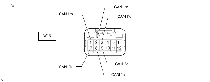
*a Front view of wire harness connector
(to No. 11 CAN Junction Connector)
*b to No. 6 CAN Junction Connector
(for Sub Bus 2 (w/o VGRS System))
(for Sub Bus 18 (w/ VGRS System))
*c to No. 9 CAN Junction Connector
(for Sub Bus 2 (w/o VGRS System))
(for Sub Bus 18 (w/ VGRS System))
*d to Lane Departure Warning Camera
(w/ Lane Departure Alert System)
(for Sub Bus 2 (w/o VGRS System))
(for Sub Bus 18 (w/ VGRS System))
-
Check the connection diagram of the components which are connected to the No. 11 CAN junction connector.
Terminal No. (Symbol) Wiring Color Connected to W13-1 (CANH) LG No. 6 CAN junction connector
(for Sub bus 2*1 or sub bus 18*2)
W13-7 (CANL) B W13-2 (CANH) BE No. 9 CAN junction connector
(for Sub bus 2*1 or sub bus 18*2)
W13-8 (CANL) B W13-3 (CANH) R Lane departure warning camera*3
(for Sub bus 2*1 or sub bus 18*2)
W13-9 (CANL) B
-
*1: w/o VGRS System
-
*2: w/ VGRS System
-
*3: w/ Lane Departure Alert System
-
-
-
-
NO. 1 CAN JUNCTION TERMINAL (w/ Seat Position Memory System, Power Tilt and Power Telescopic System, Triple Beam Headlight or Parking Assist Monitor System without Parallel Parking Assist Function)
-
Check the No. 1 CAN junction terminal.
-
Connection diagram

*a Front view of wire harness connector
(to No. 1 CAN Junction Terminal)
*b to No. 10 CAN Junction Connector
(for Sub Bus 1)
-
Check the connection diagram of the components which are connected to the No. 1 CAN junction terminal.
Terminal No. (Symbol) Wiring Color Connected to O101-3 (CANH) P No. 10 CAN junction connector
(for Sub bus 1)
O101-2 (CANL) B
-
-
-
NO. 2 CAN JUNCTION TERMINAL (w/ Network Gateway ECU)
-
Check the No. 2 CAN junction terminal.
-
Connection diagram

*a Front view of wire harness connector
(to No. 2 CAN Junction Terminal)
*b to No. 9 CAN Junction Connector
(for Sub Bus 2 (w/o VGRS System))
(for Sub Bus 18 (w/ VGRS System))
-
Check the connection diagram of the components which are connected to the No. 2 CAN junction terminal.
Terminal No. (Symbol) Wiring Color Connected to O102-3 (CANH) V No. 9 CAN junction connector
(for Sub bus 2*1 or sub bus 18*2)
O102-2 (CANL) B
-
*1: w/o VGRS System
-
*2: w/ VGRS System
-
-
-
-
NO. 3 CAN JUNCTION TERMINAL (w/ VGRS System)
-
Check the No. 3 CAN junction terminal.
-
Connection diagram

*a Front view of wire harness connector
(to No. 3 CAN Junction Terminal)
*b to No. 9 CAN Junction Connector
(for Sub Bus 19)
-
Check the connection diagram of the components which are connected to the No. 3 CAN junction terminal.
Terminal No. (Symbol) Wiring Color Connected to U55-3 (CANH) V No. 9 CAN junction connector
(for Sub bus 19)
U55-2 (CANL) B
-
-
-
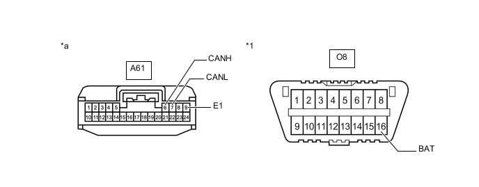
DLC3
-
Disconnect the cable from the negative (-) battery terminal.
-
Measure the resistance according to the value(s) in the table below.
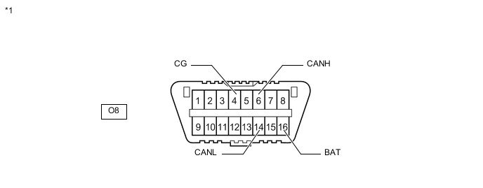
*1 DLC3 - -
-
-
ECM (for 2GR-FSE)
-
Disconnect the cable from the negative (-) battery terminal.
-
*a Rear view of wire harness connector
(to ECM)
Disconnect the A71 ECM connector.
-
Measure the resistance according to the value(s) in the table below.
-
-
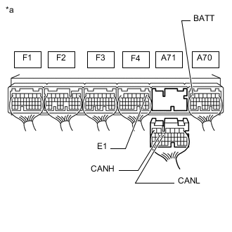
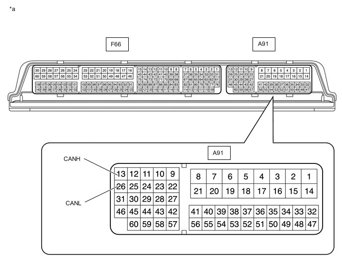
ECM (for 8AR-FTS)
*a Component without harness connected
(ECM)
- -
-
Disconnect the cable from the negative (-) battery terminal.
-
Disconnect the A91 and F66 ECM connectors.
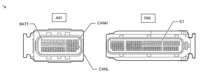
*a Front view of wire harness connector
(to ECM)
- - -
Measure the resistance according to the value(s) in the table below.
-
-
COMBINATION METER ASSEMBLY
-
Disconnect the cable from the negative (-) battery terminal.
-
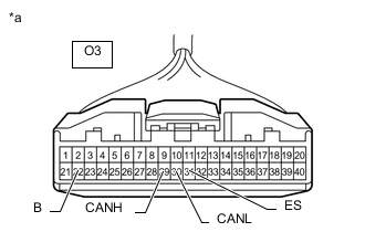
*a Front view of wire harness connector
(to Combination Meter Assembly)
Disconnect the O3 combination meter assembly connector.
-
Measure the resistance according to the value(s) in the table below.
-
-
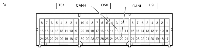
INSTRUMENT PANEL JUNCTION BLOCK ASSEMBLY AND MAIN BODY ECU (MULTIPLEX NETWORK BODY ECU)
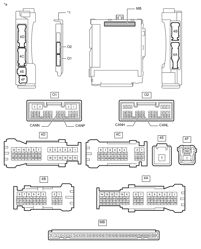
*1 Main Body ECU (Multiplex Network Body ECU) - - *a Component without harness connected
(Instrument Panel Junction Block Assembly and Main Body ECU (Multiplex Network Body ECU))
- -
-
Disconnect the cable from the negative (-) battery terminal.
-
Disconnect the O1 and O2 main body ECU (multiplex network body ECU) connectors.
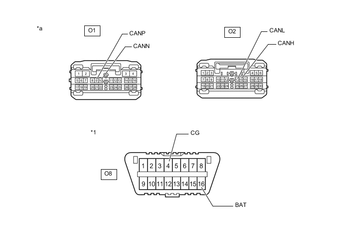
*1 DLC3 - - *a Front view of wire harness connector
(to Main Body ECU (Multiplex Network Body ECU))
- - -
Measure the resistance according to the value(s) in the table below.
-
-
SKID CONTROL ECU (BRAKE ACTUATOR ASSEMBLY)
-
Disconnect the cable from the negative (-) battery terminal.
-
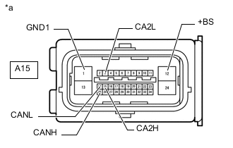
*a Front view of wire harness connector
(to Skid Control ECU (Brake Actuator Assembly))
Disconnect the A15 skid control ECU (brake actuator assembly) connector.
-
Measure the resistance according to the value(s) in the table below.
-
-
STEERING SENSOR
-
Disconnect the cable from the negative (-) battery terminal.
-
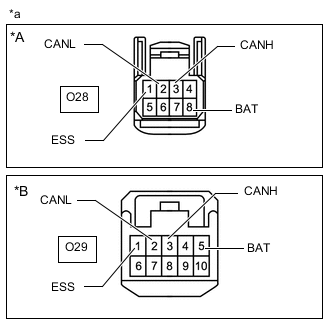
*A w/o VGRS System *B w/ VGRS System *a Front view of wire harness connector
(to Steering Sensor)
Disconnect the O28*1 or O29*2 steering sensor connector.
-
*1: w/o VGRS System
-
*2: w/ VGRS System
-
-
Measure the resistance according to the value(s) in the table below.
-
-
YAW RATE SENSOR
-
Disconnect the cable from the negative (-) battery terminal.
-
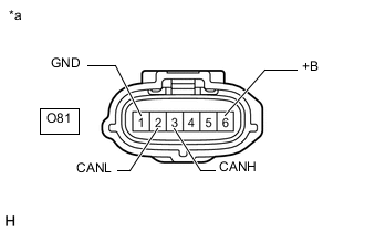
*a Front view of wire harness connector
(to Yaw Rate Sensor)
Disconnect the O81 yaw rate sensor connector.
-
Measure the resistance according to the value(s) in the table below.
-
-
POWER STEERING ECU ASSEMBLY
-
Disconnect the cable from the negative (-) battery terminal.
-
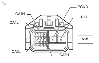
*a Front view of wire harness connector
(to Power Steering ECU Assembly)
Disconnect the A18 power steering ECU assembly connector.
-
Measure the resistance according to the value(s) in the table below.
-
-
AIRBAG SENSOR ASSEMBLY
*a Component without harness connected
(Airbag Sensor Assembly)
- -
-
Disconnect the cable from the negative (-) battery terminal.
-
Disconnect the O50 airbag sensor assembly connector.
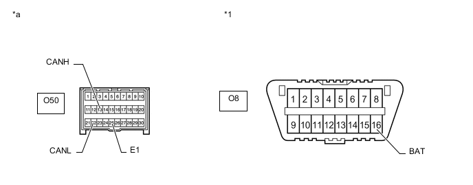
*1 DLC3 - - *a Front view of wire harness connector
(to Airbag Sensor Assembly)
- - -
Measure the resistance according to the value(s) in the table below.
-
-
CERTIFICATION ECU (SMART KEY ECU ASSEMBLY)
-
Disconnect the cable from the negative (-) battery terminal.
-
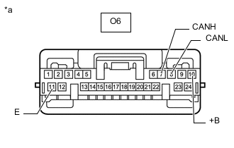
*a Front view of wire harness connector
(to Certification ECU (Smart Key ECU Assembly))
Disconnect the O6 certification ECU (smart key ECU assembly) connector.
-
Measure the resistance according to the value(s) in the table below.
-
-
RADIO RECEIVER ASSEMBLY (w/ Navigation System)
-
Disconnect the cable from the negative (-) battery terminal.
-
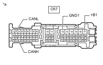
*a Front view of wire harness connector
(to Radio Receiver Assembly)
Disconnect the O57 radio receiver assembly connector.
-
Measure the resistance according to the value(s) in the table below.
-
*1: w/ Stop and Start System
-
*2: w/o Stop and Start System
-
-
-
RADIO RECEIVER ASSEMBLY (w/ Audio and Visual System with Remote Touch)
-
Disconnect the cable from the negative (-) battery terminal.
-
*a Front view of wire harness connector
(to Radio Receiver Assembly)
Disconnect the O57 radio receiver assembly connector.
-
Measure the resistance according to the value(s) in the table below.
-
*1: w/ Stop and Start System
-
*2: w/o Stop and Start System
-
-
-
RADIO RECEIVER ASSEMBLY (w/ Audio and Visual System without Remote Touch)
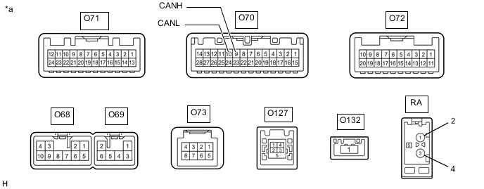
*a Component without harness connected
(Radio Receiver Assembly)
- -
-
Disconnect the cable from the negative (-) battery terminal.
-
Disconnect the O68 and O70 radio receiver assembly connectors.
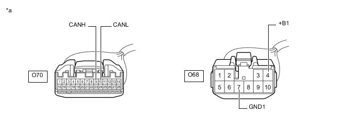
*a Front view of wire harness connector
(to Radio Receiver Assembly)
- - -
Measure the resistance according to the value(s) in the table below.
-
*1: w/ Stop and Start System
-
*2: for 6 Speakers (w/o Stop and Start System)
-
*3: for 10 Speakers (w/o Stop and Start System)
-
-
-
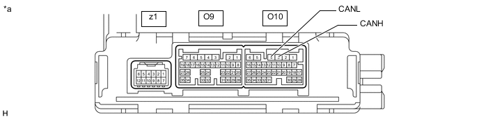
AIR CONDITIONING AMPLIFIER ASSEMBLY
*a Component without harness connected
(Air Conditioning Amplifier Assembly)
- -
-
Disconnect the cable from the negative (-) battery terminal.
-
Disconnect the O9 and O10 air conditioning amplifier assembly connectors.
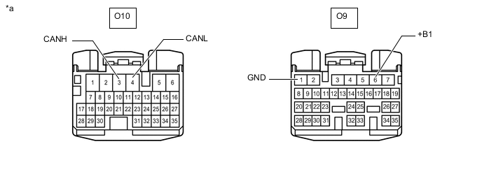
*a Front view of wire harness connector
(to Air Conditioning Amplifier Assembly)
- - -
Measure the resistance according to the value(s) in the table below.
-
-
NETWORK GATEWAY ECU (w/ Network Gateway ECU without VGRS System)
-
Disconnect the cable from the negative (-) battery terminal.
-
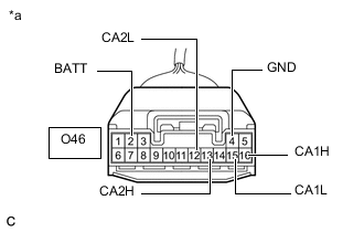
*a Front view of wire harness connector
(to Network Gateway ECU)
Disconnect the O46 network gateway ECU connector.
-
Measure the resistance according to the value(s) in the table below.
-
-
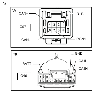
NETWORK GATEWAY ECU (w/ VGRS System)
-
Disconnect the cable from the negative (-) battery terminal.
-
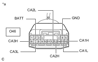
*a Front view of wire harness connector
(to Network Gateway ECU)
Disconnect the O46 network gateway ECU connector.
-
Measure the resistance according to the value(s) in the table below.
-
-
HEADLIGHT LEVELING ECU ASSEMBLY (for Single Beam Headlight)
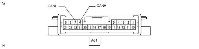
*a Component without harness connected
(Headlight Leveling ECU Assembly)
- -
-
Disconnect the cable from the negative (-) battery terminal.
-
Disconnect the A61 headlight leveling ECU assembly connector.
*1 DLC3 - - *a Front view of wire harness connector
(to Headlight Leveling ECU Assembly)
- - -
Measure the resistance according to the value(s) in the table below.
-
-
OUTER MIRROR CONTROL ECU ASSEMBLY (w/ Seat Position Memory System)
-
Disconnect the cable from the negative (-) battery terminal.
-
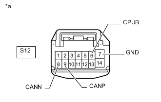
*a Front view of wire harness connector
(to Outer Mirror Control ECU Assembly (for Driver Side)) (for LHD)
(to Outer Mirror Control ECU Assembly (for Front Passenger Side)) (for RHD)
Disconnect the S12 outer mirror control ECU assembly connector.
-
Measure the resistance according to the value(s) in the table below.
-
-
OUTER MIRROR CONTROL ECU ASSEMBLY (w/ Seat Position Memory System)
-
Disconnect the cable from the negative (-) battery terminal.
-
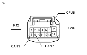
*a Front view of wire harness connector
(to Outer Mirror Control ECU Assembly (for Front Passenger Side)) (for LHD)
(to Outer Mirror Control ECU Assembly (for Driver Side)) (for RHD)
Disconnect the R12 outer mirror control ECU assembly connector.
-
Measure the resistance according to the value(s) in the table below.
-
-
POSITION CONTROL ECU AND SWITCH ASSEMBLY LH (w/ Seat Position Memory System)

*a Component without harness connected
(Position Control ECU and Switch Assembly LH)
- -
-
Disconnect the cable from the negative (-) battery terminal.
-
Disconnect the b4 and b5 position control ECU and switch assembly LH connectors.
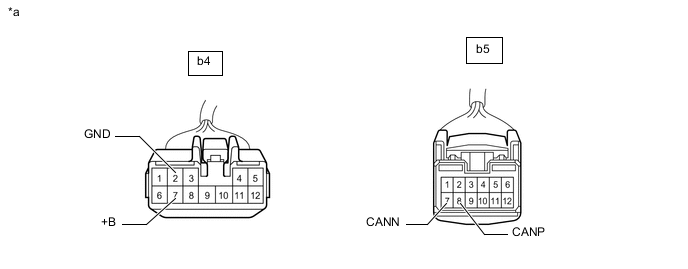
*a Front view of wire harness connector
(to Position Control ECU and Switch Assembly LH)
- - -
Measure the resistance according to the value(s) in the table below.
-
-
POSITION CONTROL ECU AND SWITCH ASSEMBLY RH (w/ Seat Position Memory System)

*a Component without harness connected
(Position Control ECU and Switch Assembly RH)
- -
-
Disconnect the cable from the negative (-) battery terminal.
-
Disconnect the a4 and a5 position control ECU and switch assembly RH connectors.

*a Front view of wire harness connector
(to Position Control ECU and Switch Assembly RH)
- - -
Measure the resistance according to the value(s) in the table below.
-
-
MULTIPLEX TILT AND TELESCOPIC ECU (w/ Power Tilt and Power Telescopic System)
-
Disconnect the cable from the negative (-) battery terminal.
-
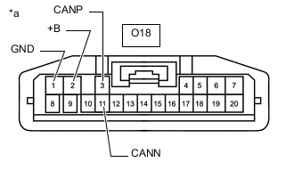
*a Front view of wire harness connector
(to Multiplex Tilt and Telescopic ECU)
Disconnect the O18 multiplex tilt and telescopic ECU connector.
-
Measure the resistance according to the value(s) in the table below.
-
-
FRONT STEERING CONTROL ECU (w/ VGRS System)
-
Disconnect the cable from the negative (-) battery terminal.
-
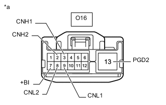
*a Front view of wire harness connector
(to Front Steering Control ECU)
Disconnect the O16 front steering control ECU connector.
-
Measure the resistance according to the value(s) in the table below.
-
-
BLIND SPOT MONITOR SENSOR LH (w/ Blind Spot Monitor System)

*a Component without harness connected
(Blind Spot Monitor Sensor LH)
- -
-
Disconnect the cable from the negative (-) battery terminal.
-
Disconnect the U47 blind spot monitor sensor LH connector.
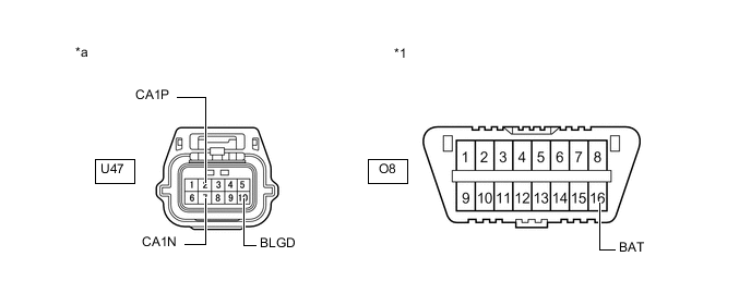
*1 DLC3 - - *a Front view of wire harness connector
(to Blind Spot Monitor Sensor LH)
- - -
Measure the resistance according to the value(s) in the table below.
-
-
DRIVING SUPPORT ECU ASSEMBLY (w/ Pre-crash Safety System)
-
Disconnect the cable from the negative (-) battery terminal.
-
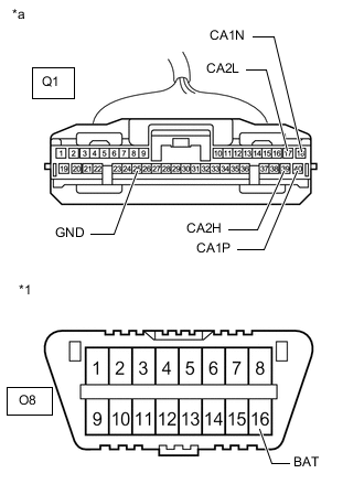
*1 DLC3 *a Front view of wire harness connector
(to Driving Support ECU Assembly)
Disconnect the Q1 driving support ECU assembly connector.
-
Measure the resistance according to the value(s) in the table below.
-
-
MILLIMETER WAVE RADAR SENSOR ASSEMBLY (w/ Pre-crash Safety System)
-
Disconnect the cable from the negative (-) battery terminal.
-
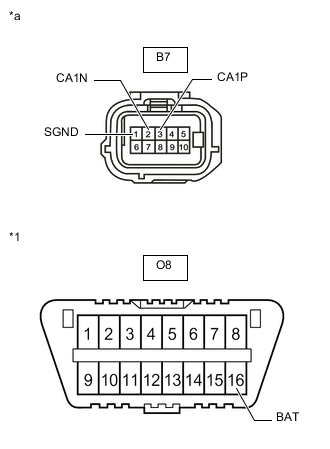
*1 DLC3 *a Front view of wire harness connector
(to Millimeter Wave Radar Sensor Assembly)
Disconnect the B7 millimeter wave radar sensor assembly connector.
-
Measure the resistance according to the value(s) in the table below.
-
-
OPTION CONNECTOR (BUS BUFFER ECU) (w/o Network Gateway ECU, or w/ Network Gateway ECU and Option Connector)
-
Disconnect the cable from the negative (-) battery terminal.
-
*A w/ Network Gateway ECU *B w/o Network Gateway ECU *a Front view of wire harness connector
(to Option Connector (Bus Buffer ECU))
Measure the resistance according to the value(s) in the table below.
-
-
CLEARANCE WARNING ECU ASSEMBLY (w/ LEXUS Parking Assist-sensor System)
-
Disconnect the cable from the negative (-) battery terminal.
-
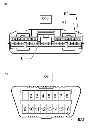
*1 DLC3 *a Front view of wire harness connector
(to Clearance Warning ECU Assembly)
Disconnect the O43 clearance warning ECU assembly connector.
-
Measure the resistance according to the value(s) in the table below.
-
-
LANE DEPARTURE WARNING CAMERA (w/ Lane Departure Alert System)
-
Disconnect the cable from the negative (-) battery terminal.
-
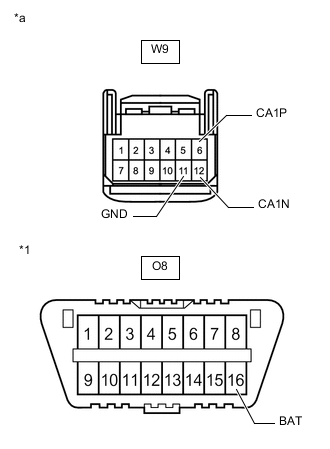
*1 DLC3 *a Front view of wire harness connector
(to Lane Departure Warning Camera)
Disconnect the W9 lane departure warning camera connector.
-
Measure the resistance according to the value(s) in the table below.
-
-
ABSORBER CONTROL ECU (w/ AVS System)
-
Disconnect the cable from the negative (-) battery terminal.
-
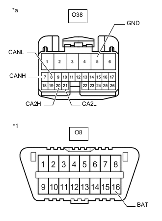
*1 DLC3 *a Front view of wire harness connector
(to Absorber Control ECU)
Disconnect the O38 absorber control ECU connector.
-
Measure the resistance according to the value(s) in the table below.
-
-
REAR STEERING CONTROL ECU (w/ VGRS System)
-
Disconnect the cable from the negative (-) battery terminal.
-
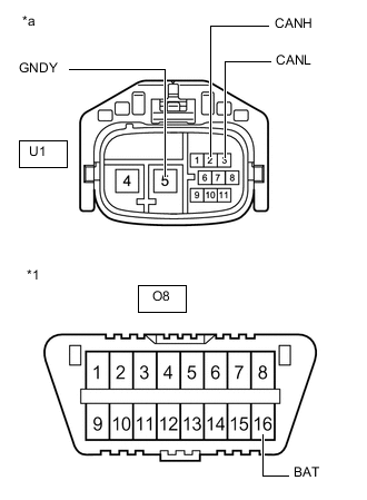
*1 DLC3 *a Front view of wire harness connector
(to Rear Steering Control ECU)
Disconnect the U1 rear steering control ECU connector.
-
Measure the resistance according to the value(s) in the table below.
-
-
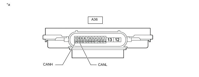
HEADLIGHT LIGHT CONTROL ECU SUB-ASSEMBLY LH (for Triple Beam Headlight)
*a Component without harness connected
(Headlight Light Control ECU Sub-assembly LH)
- -
-
Disconnect the cable from the negative (-) battery terminal.
-
Disconnect the A36 headlight light control ECU sub-assembly LH connector.
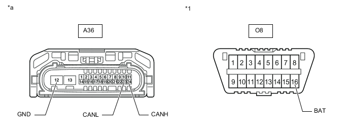
*1 DLC3 - - *a Front view of wire harness connector
(to Headlight Light Control ECU Sub-assembly LH)
- - -
Measure the resistance according to the value(s) in the table below.
-
-
STEREO COMPONENT EQUALIZER ASSEMBLY (w/ ASC System)
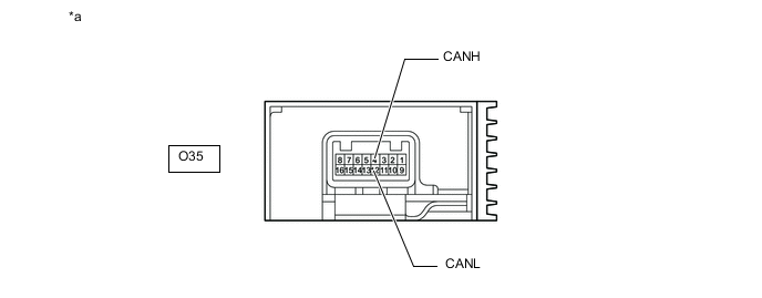
*a Component without harness connected
(Stereo Component Equalizer Assembly)
- -
-
Disconnect the cable from the negative (-) battery terminal.
-
Disconnect the O35 stereo component equalizer assembly connector.
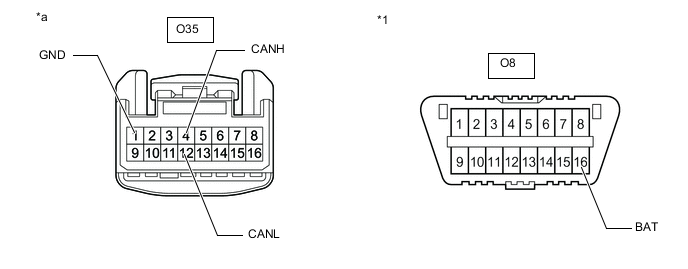
*1 DLC3 - - *a Front view of wire harness connector
(to Stereo Component Equalizer Assembly)
- - -
Measure the resistance according to the value(s) in the table below.
-
-
ENGINE STOP AND START ECU (w/ Stop and Start System)
-
Disconnect the cable from the negative (-) battery terminal.
-
Disconnect the A82 and O143 engine stop and start ECU connectors.
-
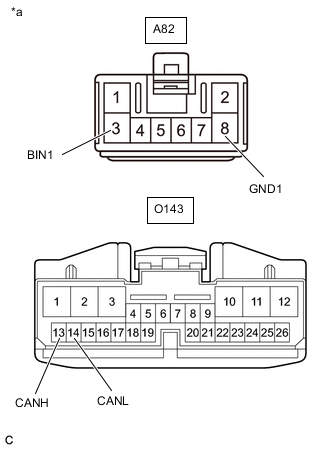
*a Front view of wire harness connector
(to Engine Stop and Start ECU)
Measure the resistance according to the value(s) in the table below.
-
-
TELEMATICS TRANSCEIVER (w/ Telematics Transceiver for G-BOOK)
-
Disconnect the cable from the negative (-) battery terminal.
-
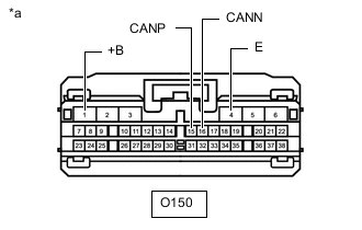
*a Front view of wire harness connector
(to Telematics Transceiver)
Disconnect the O150 telematics transceiver connector.
-
Measure the resistance according to the value(s) in the table below.
-
-
TELEMATICS TRANSCEIVER (w/ Telematics Transceiver except G-BOOK)
-
Disconnect the cable from the negative (-) battery terminal.
-
*a Front view of wire harness connector
(to Telematics Transceiver)
Disconnect the O150 telematics transceiver connector.
-
Measure the resistance according to the value(s) in the table below.
-
-
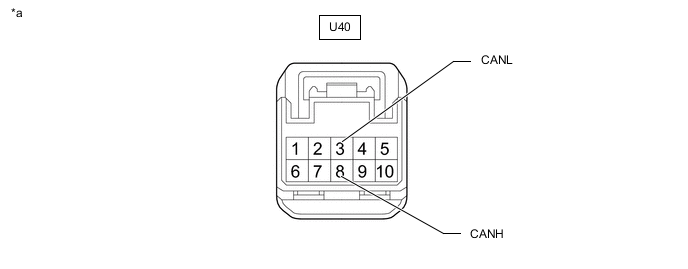
REAR TELEVISION CAMERA ASSEMBLY (w/ Parking Assist Monitor System without Parallel Parking Assist Function)
*a Component without harness connected
(Rear Television Camera Assembly)
- -
-
Disconnect the cable from the negative (-) battery terminal.
-
Disconnect the U40 rear television camera assembly connector.
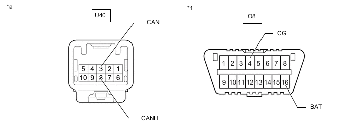
*1 DLC3 - - *a Front view of wire harness connector
(to Rear Television Camera Assembly)
- - -
Measure the resistance according to the value(s) in the table below.
-