FRONT BRAKE INSTALLATION

CAUTION / NOTICE / HINT
Tech Tips
-
Use the same procedure for the RH side and LH side.
-
The following procedure is for the LH side.
PROCEDURE
-
INSTALL FRONT DISC
-
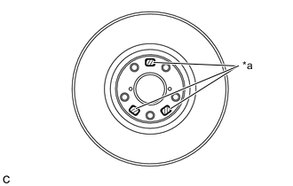
*a Identification Mark Check the identification mark to determine the installation side. (for 17 Inch Front Disc Brake)
Identification Mark Installation Position L LH Side R RH Side Note
The front disc needs to be installed to the correct side of the vehicle. There is an "L", indicating the disc for the left wheel, or an "R", indicating the disc for the right wheel, engraved on the disc in the position shown in the illustration.
-
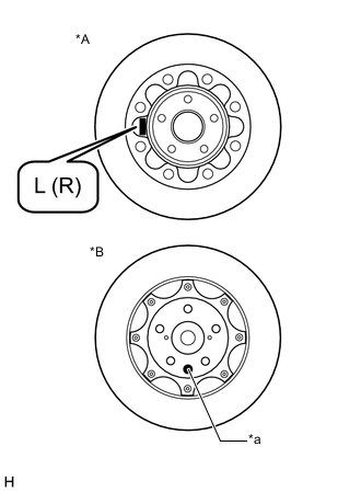
*A Inner Side of Front Disc *B Outer Side of Front Disc *a Disc Identification Paint Check the identification mark to determine the installation side. (for 18 Inch Front Disc Brake)
Note
-
The front disc needs to be installed to the correct side of the vehicle. There is an "L", indicating the disc for the left wheel, or an "R", indicating the disc for the right wheel, engraved on the inside of the disc in the position shown in the illustration.
-
There is pink paint, indicating the disc for the left wheel, or green paint, indicating the disc for the right wheel, on the surface of the front disc in the position shown in the illustration.
-
-
When reusing the front disc:
-
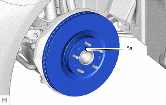
*a Matchmark Align the matchmarks of the front disc and front axle hub sub-assembly, and install the front disc.
-
-
When replacing the front disc:
-
Inspect the front disc runout.
-
Select the installation position where the front disc has minimal runout, and install the front disc.
-
-
Temporarily install the hub nut.
-
-
INSTALL FRONT DISC BRAKE CYLINDER ASSEMBLY
-
Install the front disc brake cylinder assembly to the steering knuckle with the 2 bolts.
- Torque:
- 135 N*m { 1377 kgf*cm, 100 ft.*lbf }
-
-
CONNECT FRONT FLEXIBLE HOSE
-
Connect the front flexible hose to the front disc brake cylinder assembly with a new union bolt and a new gasket.
- Torque:
- 39.2 N*m { 400 kgf*cm, 29 ft.*lbf }
Note
Install the front flexible hose lock securely into the lock hole in the front disc brake cylinder assembly.
-
-
INSTALL FRONT DISC BRAKE ANTI-SQUEAL SHIM KIT
Note
When replacing the front disc brake pads with new ones, make sure to replace the front disc brake anti-squeal shim kit at the same time.
-
for 17 Inch Front Disc Brake:
-
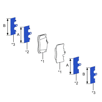
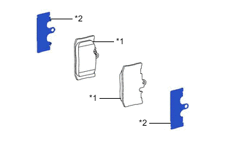
*1 Front Disc Brake Pad *2 Front No. 1 Disc Brake Anti-squeal Shim *3 Front No. 2 Disc Brake Anti-squeal Shim Install the front No. 1 disc brake anti-squeal shim and front No. 2 disc brake anti-squeal shim to each front disc brake pad.
Note
-
Make sure that the front No. 1 disc brake anti-squeal shim and front No. 2 disc brake anti-squeal shim are installed in the correct position.
-
As shown in the illustration, the front No. 1 disc brake anti-squeal shim and front No. 2 disc brake anti-squeal shim can be identified by length, with (B) being longer than (A).
-
-
-
for 18 Inch Front Disc Brake:
-
*1 Front Disc Brake Pad *2 Front No. 1 Disc Brake Anti-squeal Shim Install the front No. 1 disc brake anti-squeal shim to each front disc brake pad.
-
-
-
INSTALL FRONT DISC BRAKE PAD
-
for 17 Inch Front Disc Brake:
-
Install the 2 front disc brake pads to the front disc brake cylinder assembly.
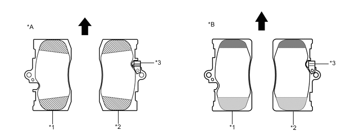
*A for Type A *B for Type B *1 Outer Pad *2 Inner Pad *3 Pad Wear Indicator - - 
Direction of Disc Rotation for Forward Movement 
Chamfered Edge (Small) 
Chamfered Edge (Large) 
Chamfered Edge (Same Size) Note
-
The upper and lower edges of the front disc brake pads are chamfered differently. Install each front disc brake pad to the correct side and in the correct position as shown in the illustration (for Type B).
-
The front disc brake pad with the pad wear indicator is positioned on the inside of the vehicle.
-
Install each front disc brake pad in the correct direction.
-
There should be no oil or grease on the friction surfaces of the front disc brake pads and front disc.
-
-
-
for 18 Inch Front Disc Brake:
-
Disc Brake Grease Lightly apply disc brake grease to the areas shown in the illustration where the front disc brake pad and front disc brake cylinder assembly contact each other.
-
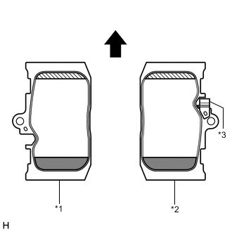
*1 Outer Pad *2 Inner Pad *3 Pad Wear Indicator Direction of Disc Rotation for Forward Movement Chamfered Edge (Small) Chamfered Edge (Large) Install the 2 front disc brake pads to the front disc brake cylinder assembly.
Note
-
The upper and lower edges of the front disc brake pads are chamfered differently. Install each front disc brake pad to the correct side and in the correct position as shown in the illustration.
-
The front disc brake pad with the pad wear indicator is positioned on the inside of the vehicle.
-
Install each front disc brake pad in the correct direction.
-
There should be no oil or grease on the friction surfaces of the front disc brake pads and front disc.
-
-
-
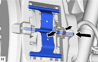
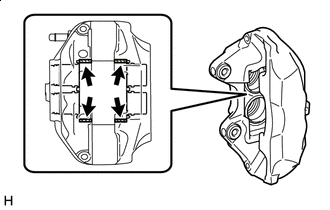
Install the front disc brake anti-rattle spring to the front disc brake cylinder assembly.
-
While pushing the front disc brake anti-rattle spring against the front disc brake cylinder assembly, install the front disc brake anti-rattle with hole pin to the front disc brake cylinder assembly.
-
Install the pin hold clip to the front disc brake anti-rattle with hole pin.
-
-
BLEED BRAKE LINE
-
INSTALL FRONT WHEEL