BRAKE BOOSTER(for LHD) INSTALLATION
PROCEDURE
-
INSTALL VACUUM SENSOR ASSEMBLY (for 8AR-FTS w/ Stop and Start System)
-
Install a new check valve grommet to the brake booster assembly.
-
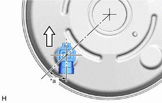
*a 45° +/- 20° 
Up Install the vacuum sensor assembly to the brake booster assembly as shown in the illustration.
-
-
INSTALL VACUUM WARNING SWITCH ASSEMBLY (for 8AR-FTS w/o Stop and Start System)
-
Install a new check valve grommet to the brake booster assembly.
-
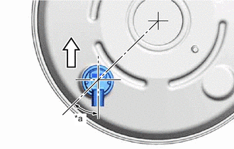
*a 45° +/- 20° Up Install the vacuum warning switch assembly to the brake booster assembly as shown in the illustration.
-
-
INSTALL BRAKE VACUUM CHECK VALVE ASSEMBLY
-
Install a new check valve grommet to the brake booster assembly.
-
Install the brake vacuum check valve assembly to the brake booster assembly.
-
-
INSTALL BRAKE MASTER CYLINDER PUSH ROD CLEVIS
-
Temporarily install the clevis lock nut and brake master cylinder push rod clevis to the brake booster assembly.
Note
Fully tighten the clevis lock nut when adjusting the brake pedal height.
-
-
INSTALL BRAKE BOOSTER GASKET
-
Install a new brake booster gasket to the brake booster assembly.
-
-
INSTALL BRAKE BOOSTER ASSEMBLY
-
Install the brake booster assembly to the vehicle body with the 4 nuts.
- Torque:
- 12.7 N*m { 130 kgf*cm, 9 ft.*lbf }
Note
Do not kink or damage the brake lines.
-
for 8AR-FTS w/ Stop and Start System:
-
Connect the connector to the vacuum sensor assembly.
-
-
for 8AR-FTS w/o Stop and Start System:
-
Connect the connector to the vacuum warning switch assembly.
-
-
-
INSTALL FRONT NO. 3 BRAKE TUBE
-
Install the front No. 3 brake tube and engage the clamp.
-
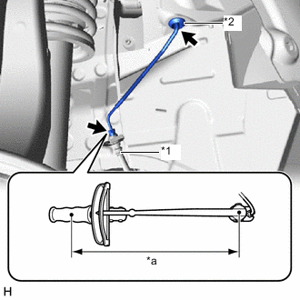
*1 Front Flexible Hose *2 Grommet *a Torque Wrench Fulcrum Length Engage the grommet.
-
Using a union nut wrench, connect the front No. 3 brake tube to the front flexible hose.
- Torque:
- Specified tightening torque
- 15.2 N*m { 155 kgf*cm, 11 ft.*lbf }
Note
-
Do not kink or damage the front No. 3 brake tube.
-
Do not allow the front No. 3 brake tube to twist or interfere with other parts or the vehicle body during tightening.
-
Do not allow any foreign matter such as dirt or dust to enter the front No. 3 brake tube from the connecting parts.
Tech Tips
-
Calculate the torque wrench reading when changing the fulcrum length of the torque wrench.
-
When using a union nut wrench (fulcrum length of 22 mm (0.866 in.)) + torque wrench (fulcrum length of 250 mm (9.84 in.)):
13.97 N*m (142 kgf*cm, 10 ft.*lbf)
-
-
INSTALL PUSH ROD PIN
-
INSTALL BRAKE PEDAL RETURN SPRING
-
Install the brake pedal return spring to the push rod pin and steering column assembly.
-
-
INSTALL BRAKE ACTUATOR WITH BRACKET
-
INSTALL REAR NO. 1 BRAKE TUBE
-
INSTALL FRONT NO. 1 BRAKE TUBE
-
CONNECT UNION TO CHECK VALVE HOSE
-
INSTALL BRAKE MASTER CYLINDER O-RING
-
INSTALL BRAKE MASTER CYLINDER SUB-ASSEMBLY
-
INSTALL WIRING HARNESS CLAMP BRACKET
-
INSTALL NO. 3 ENGINE ROOM RELAY BLOCK ASSEMBLY
-
INSTALL LOWER NO. 1 INSTRUMENT PANEL AIRBAG ASSEMBLY
-
BLEED BRAKE SYSTEM
-
INSTALL FRONT WHEEL LH
-
INSPECT AND ADJUST BRAKE PEDAL