BRAKE MASTER CYLINDER(for RHD) INSPECTION

PROCEDURE
-
INSPECT AND ADJUST BRAKE BOOSTER PUSH ROD
Note
Make the adjustment with no vacuum in the brake booster assembly. (Depress the brake pedal several times with the engine stopped.)
Tech Tips
-
Adjustment of the brake booster push rod is required when the brake master cylinder sub-assembly is replaced with a new one.
-
Adjustment is not necessary when the removed brake master cylinder sub-assembly is reused and the brake booster assembly is replaced with a new one.
-
Apply chalk to the tip of the accessory tool.
Tech Tips
The accessory tool is included with a new brake master cylinder sub-assembly.
-
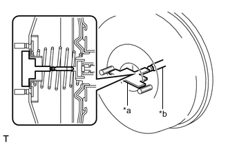
*a Accessory Tool *b Brake Booster Push Rod Place the accessory tool on the brake booster assembly.
-
Measure the clearance between the brake booster push rod and accessory tool.
Standard Clearance 0 mm (0 in.) Tech Tips
Adjust the clearance in the following cases:
-
If there is clearance between the accessory tool and the shell of the brake booster (the accessory tool does not contact the body of the brake booster), the push rod is protruding too far.
-
If the chalk does not stick on the tip of the brake booster push rod, the push rod protrusion length is insufficient.
-
-
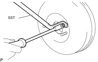
If the clearance is not as specified, adjust the push rod length by holding the push rod using SST and turning the tip of the push rod using a 7 mm socket driver.
- SST
- 09737-00020
Tech Tips
Check the push rod clearance again after adjustment.
-