VEHICLE STABILITY CONTROL SYSTEM, Diagnostic DTC:C1434

| DTC Code | DTC Name |
|---|---|
| C1434 | Steering Angle Sensor Output |
DESCRIPTION
Steering angle sensor signals are input to the skid control ECU (brake actuator assembly) via CAN communication.
Tech Tips
When a malfunction occurs in the communication line to the steering angle sensor, U0126 is output.
If a DTC related to the CAN communication line is output, first troubleshoot the CAN communication line.
DTCs may be stored if one of the following occurs:
-
Steering angle sensor zero point value malfunction.
-
Steering angle sensor signal malfunction.
-
Steering angle sensor installation abnormality.
| DTC No. | Detection Item | DTC Detection Condition | Trouble Area |
|---|---|---|---|
| C1434 | Steering Angle Sensor Output | Error in communication between the skid control ECU (brake actuator assembly) and the steering angle sensor, or abnormal steering angle sensor zero point. |
|
*: w/ Stop and Start System
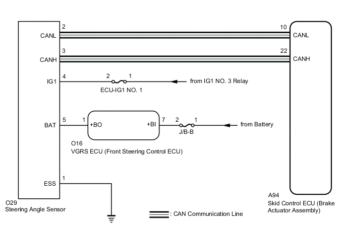
WIRING DIAGRAM
Figure 1. w/o VGRS System
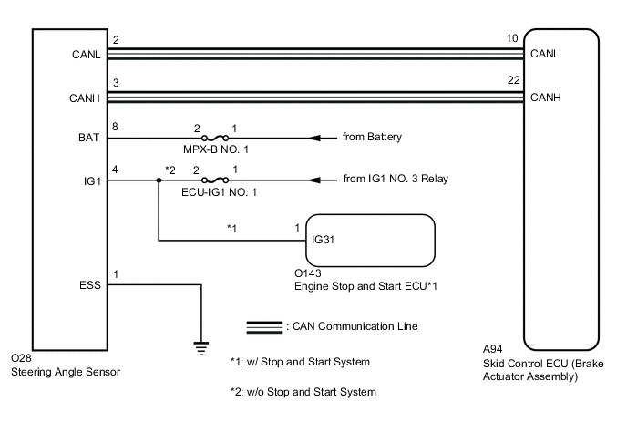
Figure 2. w/ VGRS System
CAUTION / NOTICE / HINT
Note
Inspect the fuses for circuits related to this system before performing the following procedure.
Tech Tips
-
When U0073, U0124 and/or U0126 is output together with C1434, inspect and repair the trouble areas indicated by U0073, U0124 and/or U0126 first.
-
When a speed sensor, or the yaw rate and acceleration sensor is malfunctioning, DTCs for the steering angle sensor may be stored even though the steering angle sensor is normal. When DTCs for a speed sensor, or yaw rate and acceleration sensor are output together with DTCs for the steering angle sensor, inspect and repair the speed sensor or yaw rate and acceleration sensor first, and then inspect and repair the steering angle sensor.
PROCEDURE
-
CHECK DTC
-
Clear the DTCs.
Chassis > ABS/VSC/TRC > Clear DTCs -
Turn the engine switch off.
-
Turn the engine switch on (IG) again and check that no CAN communication system DTCs are output.
-
Start the engine.
-
Drive the vehicle at a speed of 35 km/h (22 mph) and turn the steering wheel to the right and left and then check that no speed sensor or yaw rate and acceleration sensor DTCs are output.
Chassis > ABS/VSC/TRC > Trouble CodesResult Result Proceed to No CAN communication system, speed sensor, or yaw rate and acceleration sensor DTCs are output. A CAN communication system DTCs are output. B Speed sensor and/or yaw rate and acceleration sensor DTCs are output. C Tech Tips
-
If a speed sensor, or the yaw rate and acceleration sensor is malfunctioning, DTCs for the steering angle sensor may be stored even though the steering angle sensor is normal.
-
If speed sensor and yaw rate and acceleration sensor DTCs are output simultaneously, repair these malfunctions and then inspect the steering angle sensor.
-
B 
INSPECT CAN COMMUNICATION SYSTEM Click here
C
REPAIR CIRCUITS INDICATED BY OUTPUT DTCS Click here
A 
-
-
CHECK STEERING ANGLE SENSOR INSTALLATION
-
Turn the engine switch off.
-
Check that the steering angle sensor has been installed properly.
OK The steering angle sensor installation is normal. Result Result Proceed to OK (w/o VGRS System) A OK (w/ VGRS System) B NG C
B 
CHECK HARNESS AND CONNECTOR (BAT TERMINAL) Click here
C
INSTALL STEERING ANGLE SENSOR CORRECTLY Click here
A
-
-
CHECK HARNESS AND CONNECTOR (BAT TERMINAL)
-
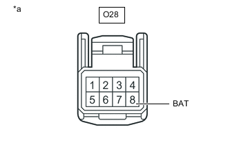
*a Front view of wire harness connector
(to Steering Angle Sensor)
Remove the steering wheel and the column cover lower.
-
Make sure that there is no looseness at the locking part and the connecting part of the connector.
-
Disconnect the O28 steering angle sensor connector.
-
Measure the voltage according to the value(s) in the table below.
Standard Voltage Tester Connection Condition Specified Condition O28-8 (BAT) - Body ground Always 11 to 14 V Result Result Proceed to OK (w/ Stop and Start System) A OK (w/o Stop and Start System) B NG C
B
CHECK HARNESS AND CONNECTOR (IG1 TERMINAL) Click here
C
REPAIR OR REPLACE HARNESS OR CONNECTOR (BAT CIRCUIT)
A
-
-
CHECK HARNESS AND CONNECTOR (IG1 TERMINAL)
-
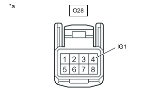
*a Front view of wire harness connector
(to Steering Angle Sensor)
Turn the engine switch on (IG).
-
Measure the voltage according to the value(s) in the table below.
Standard Voltage Tester Connection Condition Specified Condition O28-4 (IG1) - Body ground Engine switch on (IG) 10.5 to 16 V Result Proceed to OK NG
NG
INSPECT STOP AND START SYSTEM (BACKUP BOOST CONVERTER CIRCUIT) Click here
OK
-
-
CHECK HARNESS AND CONNECTOR (ESS TERMINAL)
-
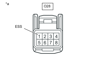
*a Front view of wire harness connector
(to Steering Angle Sensor)
Turn the engine switch off.
-
Measure the resistance according to the value(s) in the table below.
Note
Before measuring the resistance of the steering angle sensor, turn the engine switch off and leave the vehicle for 1 minute or more without operating the key or switches, or opening or closing the doors.
Standard Resistance Tester Connection Condition Specified Condition O28-1 (ESS) - Body ground 1 minute after engine switch off Below 1 Ω Result Proceed to OK NG Tech Tips
If troubleshooting has been carried out according to Problem Symptoms Table, refer back to the table and proceed to the next step before replacing parts.
OK
REPLACE STEERING ANGLE SENSOR Click here
NG
REPAIR OR REPLACE HARNESS OR CONNECTOR (ESS CIRCUIT)
-
-
CHECK HARNESS AND CONNECTOR (IG1 TERMINAL)
-
*a Front view of wire harness connector
(to Steering Angle Sensor)
Turn the engine switch on (IG).
-
Measure the voltage according to the value(s) in the table below.
Standard Voltage Tester Connection Condition Specified Condition O28-4 (IG1) - Body ground Engine switch on (IG) 11 to 14 V Result Proceed to OK NG
OK
GO TO STEP 5 Click here
NG
REPAIR OR REPLACE HARNESS OR CONNECTOR (IG1 CIRCUIT)
-
-
CHECK HARNESS AND CONNECTOR (BAT TERMINAL)
-
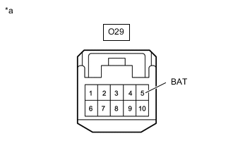
*a Front view of wire harness connector
(to Steering Angle Sensor)
Remove the steering wheel and the column cover lower.
-
Make sure that there is no looseness at the locking part and the connecting part of the connector.
-
Disconnect the O29 steering angle sensor connector.
-
Measure the voltage according to the value(s) in the table below.
Standard Voltage Tester Connection Condition Specified Condition O29-5 (BAT) - Body ground Always 11 to 14 V Result Proceed to OK NG
NG
REPAIR OR REPLACE HARNESS OR CONNECTOR (BAT CIRCUIT)
OK
-
-
CHECK HARNESS AND CONNECTOR (IG1 TERMINAL)
-
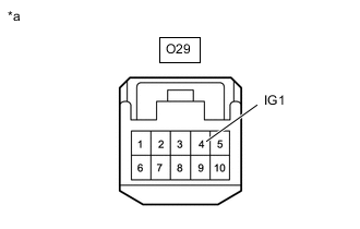
*a Front view of wire harness connector
(to Steering Angle Sensor)
Turn the engine switch on (IG).
-
Measure the voltage according to the value(s) in the table below.
Standard Voltage Tester Connection Condition Specified Condition O29-4 (IG1) - Body ground Engine switch on (IG) 11 to 14 V Result Proceed to OK NG
NG
REPAIR OR REPLACE HARNESS OR CONNECTOR (IG1 CIRCUIT)
OK
-
-
CHECK HARNESS AND CONNECTOR (ESS TERMINAL)
-
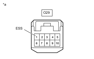
*a Front view of wire harness connector
(to Steering Angle Sensor)
Turn the engine switch off.
-
Measure the resistance according to the value(s) in the table below.
Note
Before measuring the resistance of the steering angle sensor, turn the engine switch off and leave the vehicle for 1 minute or more without operating the key, switches or opening or closing the doors.
Standard Resistance Tester Connection Condition Specified Condition O29-1 (ESS) - Body ground 1 minute after engine switch off Below 1 Ω Result Proceed to OK NG Tech Tips
If troubleshooting has been carried out according to Problem Symptoms Table, refer back to the table and proceed to the next step before replacing parts.
OK
REPLACE STEERING ANGLE SENSOR Click here
NG
REPAIR OR REPLACE HARNESS OR CONNECTOR (ESS CIRCUIT)
-