REAR SHOCK ABSORBER REMOVAL

CAUTION / NOTICE / HINT
Tech Tips
-
Use the same procedure for the RH side and LH side.
-
The following procedure is for the LH side.
PROCEDURE
-
REMOVE LUGGAGE COMPARTMENT TRIM COVER
-
REMOVE REAR WHEEL
-
REMOVE REAR SUSPENSION ARM COVER
-
SEPARATE TOE CONTROL LINK SUB-ASSEMBLY (w/o Dynamic Rear Steering)
-
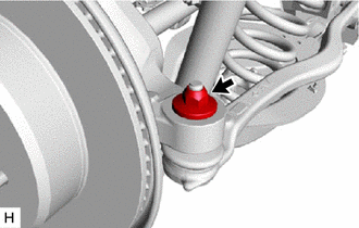
Remove the nut.
-
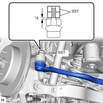
*a 1 mm or more Install 2 spacers (SST spacer B) as shown in the illustration.
- SST
- 09960-20010 ( 09961-02060 )
Note
As SST may be damaged, make sure that the clearance between the rear axle assembly and spacers is 1 mm (0.0394 in.) or more.
-
Using SST, separate the toe control link sub-assembly from the rear axle assembly as shown in the illustration.
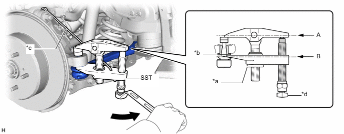
*a Nut *b Spacer *c Tie string without any slack *d Place wrench here 
Turn 
Molybdenum Grease - SST
- 09960-20010 ( 09961-02010, 09961-02060 )
CAUTION:
Apply molybdenum grease to the threads and tip of the SST bolt.
Note
-
Install SST so that A and B are parallel.
-
Be sure to place the wrench on the part indicated in the illustration.
-
Be sure to tighten the string firmly to secure SST to the rear upper control arm assembly to prevent SST from falling off.
-
Do not damage the toe control link sub-assembly ball joint dust cover.
-
Make sure that SST is securely positioned on the spacer.
-
If the spacer has come off, replace the rear axle carrier sub-assembly with a new one.
-
-
SEPARATE REAR STEERING TIE ROD ASSEMBLY (w/ Dynamic Rear Steering)
-
REMOVE ABSORBER CONTROL ACTUATOR (w/ AVS)
-
REMOVE REAR SHOCK ABSORBER ASSEMBLY
-
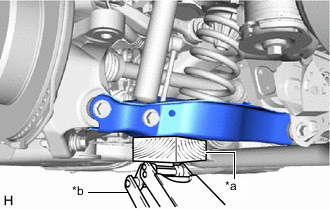
*a Wooden Block *b Jack Support the rear No. 2 suspension arm assembly using a jack and wooden block.
Note
-
When jacking up the rear No. 2 suspension arm assembly, be sure to jack it up slowly.
-
Make sure to perform this operation with the vehicle kept as low as possible.
-
Keep supporting the rear No. 2 suspension arm assembly with a jack until the installation of the rear shock absorber assembly has been completed.
-
-
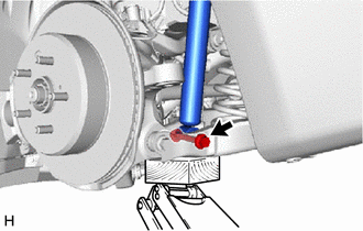
Remove the bolt and nut, and separate the rear shock absorber assembly from the rear No. 2 suspension arm assembly.
Note
Because the nut has its own stopper, do not turn the nut. Loosen the bolt with the nut secured.
-
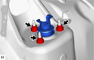
Remove the 3 nuts and rear shock absorber assembly from the vehicle body.
-
-
REMOVE REAR SUSPENSION SUPPORT ASSEMBLY
-
w/o AVS:
-
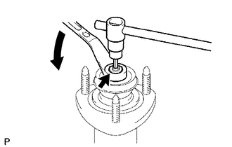
Using a 6 mm hexagon socket wrench, secure the rear shock absorber assembly rod and remove the rear support to rear shock absorber nut using a wrench.
Note
Securely insert the 6 mm hexagon socket wrench into the rear shock absorber assembly rod to prevent damage to the rear shock absorber assembly when removing the rear support to rear shock absorber nut.
-
Remove the rear shock absorber cushion washer, rear No. 1 shock absorber cushion, rear suspension support assembly and rear No. 2 shock absorber cushion from the rear shock absorber assembly.
-
-
w/ AVS:
-
Secure the rear actuator support bracket of the rear shock absorber assembly between aluminum plates in a vise.
Note
Do not overtighten the vise.
-
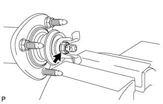
Remove the rear support to rear shock absorber nut and rear actuator support bracket from the rear shock absorber assembly.
-
Remove the rear shock absorber cushion washer, rear No. 1 shock absorber cushion, rear suspension support assembly and rear No. 2 shock absorber cushion from the rear shock absorber assembly.
-
-
-
REMOVE REAR NO. 1 SPRING BUMPER
-
Remove the rear No. 1 spring bumper from the rear shock absorber assembly.
-