FRONT SUSPENSION MEMBER REMOVAL
PROCEDURE
-
REMOVE FRONT SUSPENSION CROSSMEMBER SUB-ASSEMBLY
-
REMOVE FRONT ENGINE MOUNTING INSULATOR
-
REMOVE ENGINE UNDER COVER SUB-ASSEMBLY LH
-
Remove the engine under cover sub-assembly LH.
-
-
REMOVE ENGINE UNDER COVER SUB-ASSEMBLY RH
Tech Tips
Perform the same procedure as for the LH side.
-
REMOVE FRONT STABILIZER BAR
-
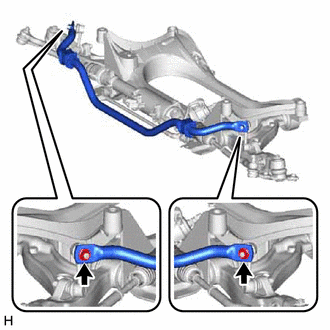
Remove the 2 nuts and front stabilizer bar.
Tech Tips
If the ball joint turns together with the nut, use a 6 mm hexagon socket wrench to hold the stud bolt.
-
-
SEPARATE FRONT LOWER SUSPENSION ARM ASSEMBLY LH
-
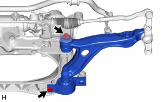
Remove the 2 bolts, 2 nuts and washer, and separate the front lower suspension arm assembly LH.
-
-
SEPARATE FRONT LOWER SUSPENSION ARM ASSEMBLY RH
Tech Tips
Perform the same procedure as for the LH side.
-
REMOVE POWER STEERING LINK ASSEMBLY
-
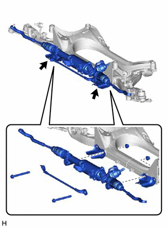
Remove the 2 bolts, 2 nuts, No. 1 steering rack housing bracket, 2 front suspension member brace plates and power steering link assembly from the front suspension crossmember sub-assembly.
Tech Tips
Remove the power steering link assembly together with the front lower suspension arm assembly LH and front lower suspension arm assembly RH.
-