FRONT SHOCK ABSORBER REMOVAL

CAUTION / NOTICE / HINT
Tech Tips
-
Use the same procedure for the RH side and LH side.
-
The following procedure is for the LH side.
PROCEDURE
-
REMOVE FRONT WHEEL
-
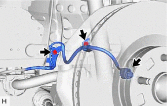
SEPARATE FRONT SKID CONTROL SENSOR WIRE
-
Disconnect the front skid control sensor wire connector from the front axle hub sub-assembly.
-
Remove the 2 bolts and separate the front skid control sensor wire from the front shock absorber with coil spring and vehicle body.
Note
Be careful not to deform the bracket of the front shock absorber with coil spring when removing the bolt.
-
-
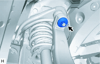
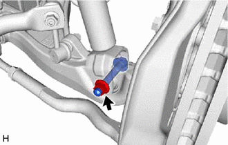
REMOVE FRONT STABILIZER LINK ASSEMBLY
-
SEPARATE FRONT UPPER SUSPENSION ARM ASSEMBLY
-
Remove the clip and nut.
-
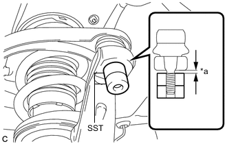
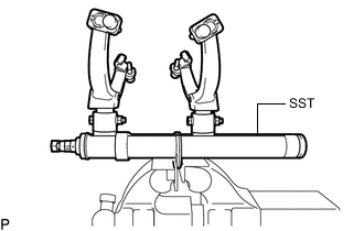
*a 1 mm (0.0394 in.) Install SST to the front upper suspension arm assembly as shown in the illustration.
- SST
- 09960-20010 ( 09961-02060 )
Note
Check that the clearance measurement between SST and the steering knuckle is 1 mm (0.0394 in.).
-
Using SST, separate the front upper suspension arm assembly from the steering knuckle.
- SST
- 09960-20010 ( 09961-02010 )
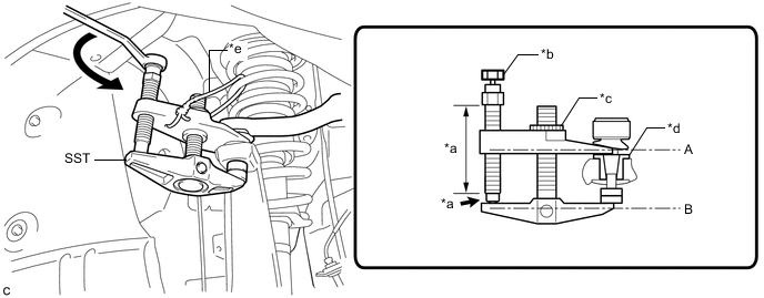
*a Molybdenum grease application area *b Place wrench here *c Center Nut *d Spacer *e String - - CAUTION:
Apply molybdenum grease to the threads and end of the SST bolt.
Note
-
Install SST with the center nut so that (A) and (B) shown in the illustration are parallel. Otherwise, the front upper suspension arm dust cover may be damaged.
-
Be sure to place a wrench on the part indicated in the illustration.
-
Do not damage the ball joint dust cover.
-
Do not damage the steering knuckle.
-
Make sure that SST is securely positioned on the spacer.
-
Be sure to tighten the string firmly to secure SST to the front upper suspension arm assembly to prevent SST from falling off.
If the steering knuckle spacer has come off, replace the steering knuckle with a new one.
-
-
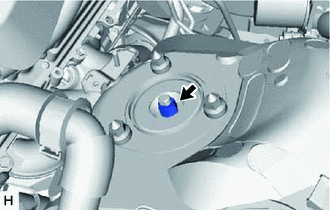
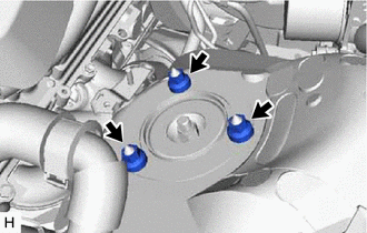
REMOVE UPPER SHOCK ABSORBER CAP (w/ AVS)
-
REMOVE ABSORBER CONTROL ACTUATOR (w/ AVS)
-
REMOVE FRONT SHOCK ABSORBER WITH COIL SPRING
-
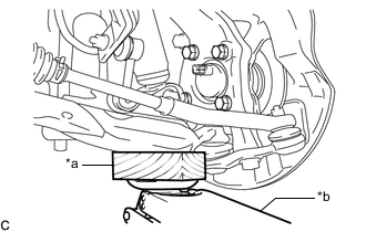
*a Wooden Block *b Jack Support the front lower suspension arm assembly using a jack and wooden block.
-
Remove the nut.
Note
-
Because the nut has its own stopper, do not turn the nut. Loosen the bolt with the nut secured.
-
Do not remove the bolt.
-
-
Loosen the lock nut.
Note
-
Do not remove the lock nut.
-
Loosen the lock nut only when the front shock absorber with coil spring needs to be disassembled.
-
-
Remove the 3 nuts from the front shock absorber with coil spring (upper side).
-
Remove the front No. 3 spring support reinforcement.
-
Remove the bolt from the front shock absorber with coil spring (lower side).
-
Slowly lower the jack and remove the front shock absorber with coil spring.
-
-
REMOVE FRONT SHOCK ABSORBER ASSEMBLY
-
For SST with stopper pins:
-
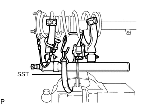
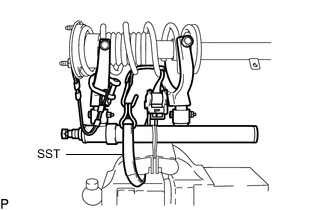
Secure SST in a vise.
- SST
- 09727-30022 ( 09727-00010, 09727-00022, 09727-00031 )
-
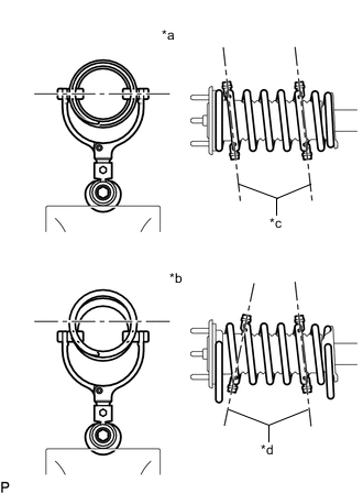
*a Correct *b Incorrect *c Parallel *d Not Parallel Attach the hooks of each SST arm across the diameter of the coil spring.
CAUTION:
-
Make sure that the hooks of the upper and lower arms are attached to the coil spring so that the distance between the hooks is as large as possible.
-
Make sure that the arms of SST are parallel and attached to the coil spring, and the number of coil springs between the hooks on each side is the same.
-
Check that the claws of the hooks are securely attached to the coil spring.
-
-
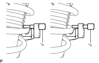
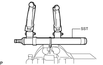
*a Correct *b Incorrect *c Stopper Pin Install the stopper pins to the hooks of SST.
CAUTION:
Make sure that the stopper pins are installed securely.
-
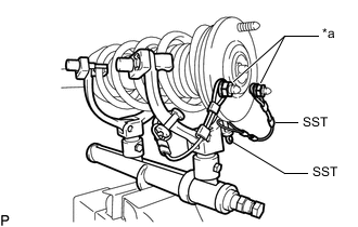
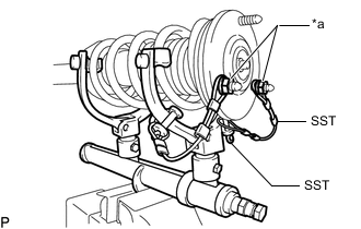
*a Vehicle Nut Install SST and 2 vehicle nuts to the upper support as shown in the illustration.
- SST
- 09727-30022 ( 09727-00090, 09727-00100 )
-
Using SST, compress the coil spring.
CAUTION:
-
If the coil spring bends while using SST, stop immediately and reattach SST correctly.
-
Do not compress the coil spring to the point where the coils touch each other.
-
Do not use an impact wrench.
-
If a stopper pin touches the coil spring while using SST, remove the stopper pin and continue with the procedure. In this case, installing the coil spring stopper belt as shown in the illustration is recommended.
- SST
- 09727-00110
-
-
Check that the coil spring has become detached, and then remove the lock nut.
CAUTION:
Do not remove the lock nut if the coil spring is not free.
-
-
For SST without stopper pins:
-
Secure SST in a vise.
- SST
- 09727-30021 ( 09727-00010, 09727-00021, 09727-00031 )
-
*a Correct *b Incorrect *c Parallel *d Not Parallel Attach the hooks of each SST arm across the diameter of the coil spring.
CAUTION:
-
Make sure that the hooks of the upper and lower arms are attached to the coil spring so that the distance between the hooks is as large as possible.
-
Make sure that the arms of SST are parallel and attached to the coil spring, and the number of coil springs between the hooks on each side is the same.
-
Check that the claws of the hooks are securely attached to the coil spring.
-
-
*a Vehicle Nut Install SST and 2 vehicle nuts to the upper support as shown in the illustration.
- SST
- 09727-30021 ( 09727-00090, 09727-00100 )
-
Using SST, compress the coil spring.
CAUTION:
-
If the coil spring bends while using SST, stop immediately and reattach SST correctly.
-
Do not compress the coil spring to the point where the coils touch each other.
-
Do not use an impact wrench.
Tech Tips
Installing SST as shown in the illustration is recommended.
- SST
- 09727-00110
-
-
Check that the coil spring has become detached, and then remove the lock nut.
CAUTION:
Do not remove the lock nut if the coil spring is not free.
-
-
w/ AVS:
-
Remove the front actuator support bracket from the front shock absorber assembly.
-
-
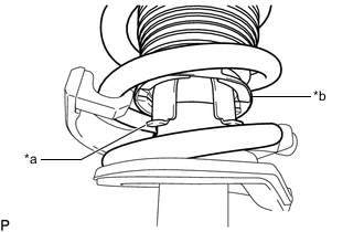
*a Front Shock Absorber Assembly Claw *b End of Front Upper Coil Spring Insulator Remove the front suspension support assembly from the front shock absorber assembly.
Note
Turn the front suspension support assembly to disengage the end of the front upper coil spring insulator from the front shock absorber assembly claws.
-
Remove the front upper coil spring insulator from the front suspension support assembly.
-
Remove the front spring bumper from the front suspension support assembly.
-
Remove the front coil spring and SST.
Note
Do not use an impact wrench. It will damage SST.
-
Remove the front lower coil spring insulator from the front shock absorber assembly.
-