AUTOMATIC TRANSMISSION UNIT(for 2GR) INSPECTION

PROCEDURE
-
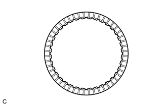
INSPECT NO. 1 BRAKE DISC
-
Check if the contact surfaces of the No. 1 brake discs, No. 1 brake plates and the No. 1 brake flange are worn or burnt.
If necessary, replace them.
Note
-
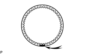
If the lining of any No. 1 brake disc is peeled or discolored, or even if part of the printed number is damaged, replace all the No. 1 brake discs.
-
Before installing new No. 1 brake discs, soak them in ATF for at least 2 hours.
-
-
-
INSPECT FRONT PLANETARY GEAR ASSEMBLY
-
Using a feeler gauge, measure the clearance between the front planetary gear assembly and each pinion gear.
Standard Clearance 0.2 to 0.6 mm (0.00787 to 0.0236 in.)
-
If the clearance is not as specified, replace the front planetary gear assembly.
-
-
-
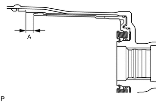
INSPECT PACK CLEARANCE OF NO. 1 BRAKE
-
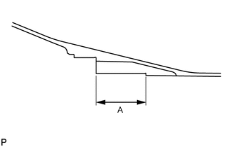
Using a vernier caliper, measure the distance (Dimension (A)) between the installation surface of the oil pump assembly and the installation surface the No. 1 brake flange shown in the illustration at several points, and calculate the average.
Tech Tips
Dimension (A) = 59.77 to 60.03 mm (2.35 to 2.36 in.)
-
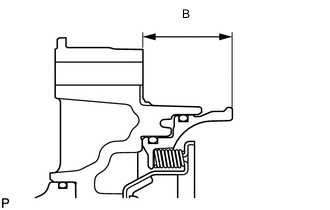
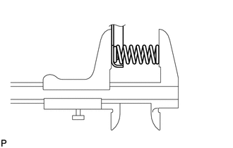
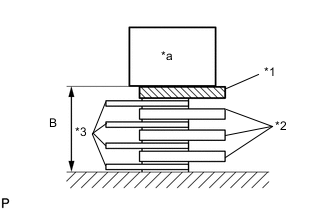
Using a vernier caliper, measure the distance (Dimension (B)) between the front of the oil pump assembly and the front of the No. 1 brake piston shown in the illustration at several points, and calculate the average.
Tech Tips
Dimension (B) = 34.636 to 34.964 mm (1.36 to 1.38 in.)
-
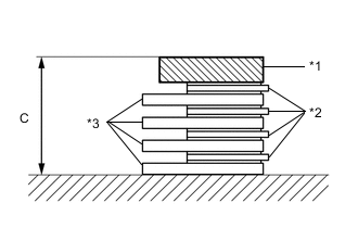
*1 No. 1 Brake Flange *2 No. 1 Brake Disc *3 No. 1 Brake Plate Using a vernier caliper, measure the thickness (Dimension (C)) of the 4 No. 1 brake plates, 4 No. 1 brake discs, and No. 1 brake flange, when assembled.
Tech Tips
-
Dimension (C) = 19.41 to 21.11 mm (0.764 to 0.831 in.)
-
Standard Clearance = Dimension (A) - Dimension (B) - Dimension (C)
Standard Clearance 0.75 to 1.05 mm (0.0296 to 0.0413 in.) -
-
If the clearance is not as specified, select and install a No. 1 brake flange that will bring the clearance within the specified range.
Tech Tips
There are 9 No. 1 brake flanges of different thickness.
No. 1 Brake Flange Thickness Part No. Mark Thickness 35676-50070 0 4.45 to 4.55 mm (0.175 to 0.179 in.) 35676-50080 1 4.55 to 4.65 mm (0.179 to 0.183 in.) 35676-50090 2 4.65 to 4.75 mm (0.183 to 0.187 in.) 35676-50100 3 4.75 to 4.85 mm (0.187 to 0.191 in.) 35676-50110 4 4.85 to 4.95 mm (0.191 to 0.195 in.) 35676-50120 5 4.95 to 5.05 mm (0.195 to 0.199 in.) 35676-50130 6 5.05 to 5.15 mm (0.199 to 0.203 in.) 35676-50140 7 5.15 to 5.25 mm (0.203 to 0.207 in.) 35676-50150 8 5.25 to 5.35 mm (0.207 to 0.211 in.)
-
-
INSPECT NO. 3 CLUTCH DISC
-
Check if the contact surfaces of the No. 3 clutch discs, No. 3 clutch plates and the No. 3 clutch flange are worn or burnt.
If necessary, replace them.
Note
Before installing new No. 3 clutch discs, soak them in ATF for at least 2 hours.
-
-
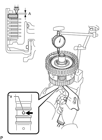
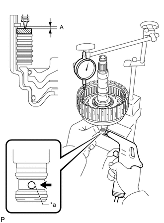
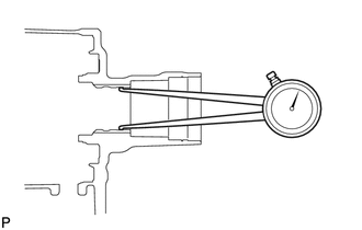
INSPECT PACK CLEARANCE OF NO. 3 CLUTCH
-
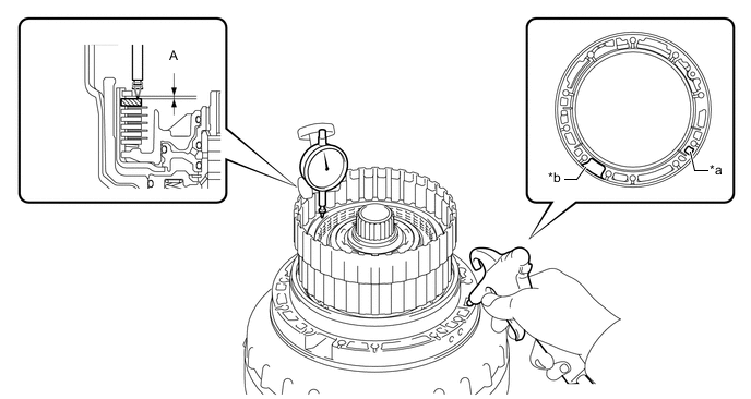
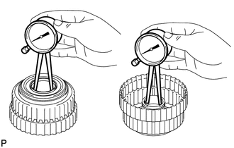
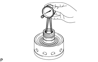
Using a dial indicator, measure the clearance (Dimension (A)) of the No. 3 clutch at several points while applying compressed air (196 kPa, 2.0 kgf/cm2, 28 psi) to the oil hole as shown in the illustration, and calculate the average.
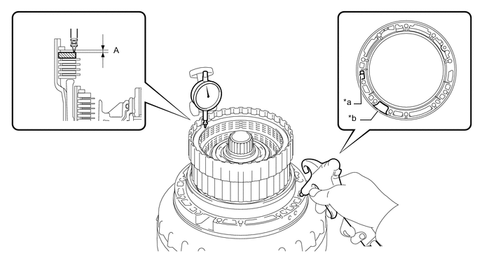
*a Oil Hole *b Speed Sensor Hole Standard Clearance 0.4 to 0.7 mm (0.0158 to 0.0275 in.) If the clearance is not as specified, select and install an appropriate No. 3 clutch flange that will bring the clearance within the specified range.
Tech Tips
There are 7 No. 3 clutch flanges of different thicknesses.
No. 3 Clutch Flange Thickness Part No. Mark Thickness 34615-50060 0 3.95 to 4.05 mm (0.156 to 0.159 in.) 34615-50070 1 4.05 to 4.15 mm (0.159 to 0.163 in.) 34615-50080 2 4.15 to 4.25 mm (0.163 to 0.167 in.) 34615-50090 3 4.25 to 4.35 mm (0.167 to 0.171 in.) 34615-50100 4 4.35 to 4.45 mm (0.171 to 0.175 in.) 34615-50110 5 4.45 to 4.55 mm (0.175 to 0.179 in.) 34615-50120 6 4.55 to 4.65 mm (0.179 to 0.183 in.)
-
-
INSPECT REVERSE CLUTCH DISC
-
Check if the contact surfaces of the reverse clutch discs, reverse clutch plates and the reverse clutch flange are worn or burnt.
If necessary, replace them.
Note
-
If the lining of any No. 1 brake disc is peeled or discolored, or even if part of the printed number is damaged, replace all the No. 1 brake discs..
-
Before installing new reverse clutch discs, soak them in ATF for at least 2 hours.
-
-
-
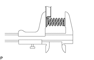
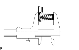
INSPECT REVERSE CLUTCH RETURN SPRING SUB-ASSEMBLY
-
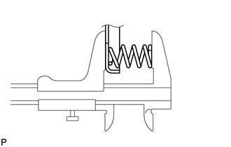
Using a vernier caliper, measure the free length of the reverse clutch return spring sub-assembly including the spring seat.
Standard Free Length 22.21 mm (0.874 in.)
-
If the free length is not as specified, replace the reverse clutch return spring sub-assembly.
-
-
-
INSPECT PACK CLEARANCE OF REVERSE CLUTCH
-
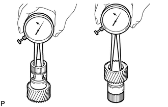
Using a dial indicator, measure the clearance (Dimension (A)) of the reverse clutch at several points while applying compressed air (196 kPa, 2.0 kgf/cm2, 28 psi) to the oil hole as shown in the illustration, and calculate the average.
*a Oil Hole *b Speed Sensor Hole Standard Clearance 0.5 to 0.8 mm (0.0197 to 0.0315 in.) If the clearance is not as specified, select and install an appropriate reverse clutch flange that will bring the clearance within the specified range.
Tech Tips
There are 9 reverse clutch flanges of different thicknesses.
Reverse Clutch Flange Thickness Part No. Mark Thickness 35649-50080 0 2.95 to 3.05 mm (0.116 to 0.120 in.) 35649-50090 1 3.05 to 3.15 mm (0.120 to 0.124 in.) 35649-50100 2 3.15 to 3.25 mm (0.124 to 0.128 in.) 35649-50110 3 3.25 to 3.35 mm (0.128 to 0.132 in.) 35649-50120 4 3.35 to 3.45 mm (0.132 to 0.136 in.) 35649-50130 5 3.45 to 3.55 mm (0.136 to 0.140 in.) 35649-50140 6 3.55 to 3.65 mm (0.140 to 0.144 in.) 35649-50150 7 3.65 to 3.75 mm (0.144 to 0.148 in.) 35649-50160 8 3.75 to 3.85 mm (0.148 to 0.152 in.)
-
-
INSPECT OVERDRIVE CLUTCH RETURN SPRING SUB-ASSEMBLY
-
Using a vernier caliper, measure the free length of the overdrive clutch return spring sub-assembly including the spring seat.
Standard Free Length 21.09 mm (0.830 in.)
-
If the free length is not as specified, replace the overdrive clutch return spring sub-assembly.
-
-
-
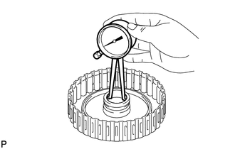
INSPECT OVERDRIVE DIRECT CLUTCH DRUM SUB-ASSEMBLY
-
Using a caliper gauge, measure the inside diameter of the overdrive direct clutch drum sub-assembly bushing.
Standard Inside Diameter (Front Side) 67.40 to 67.44 mm (2.65 to 2.66 in.) Standard Inside Diameter (Rear Side) 55.62 to 55.64 mm (2.18976 to 2.19055 in.)
-
If the inside diameter is not as specified, replace the overdrive direct clutch drum sub-assembly.
-
-
-
INSPECT FORWARD MULTIPLE CLUTCH DISC
-
Check if the contact surfaces of the forward multiple clutch discs, forward multiple clutch plates, forward clutch flange and the clutch cushion plate are worn or burnt.
If necessary, replace them.
Note
-
If the lining of any forward multiple clutch disc is peeled or discolored, or even if part of the printed number is damaged, replace all the forward multiple clutch discs.
-
Before installing new forward multiple clutch discs, soak them in ATF for at least 2 hours.
-
-
-
INSPECT FORWARD CLUTCH RETURN SPRING SUB-ASSEMBLY
-
Using a vernier caliper, measure the free length of the forward clutch return spring sub-assembly including the spring seat.
Standard Free Length 20.82 mm (0.820 in.)
-
If the free length is not as specified, replace the forward clutch return spring sub-assembly.
-
-
-
INSPECT PACK CLEARANCE OF FORWARD MULTIPLE CLUTCH
-
Temporarily install the front planetary gear assembly to the forward clutch drum sub-assembly.
-
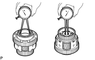
*a Oil Hole Using a dial indicator, measure the clearance (Dimension (A)) of the forward multiple clutch at multiple points while applying compressed air (196 kPa, 2.0 kgf/cm2, 28 psi) to the oil hole as shown in the illustration, and calculate the average.
Standard Clearance 0.90 to 1.20 mm (0.0354 to 0.0472 in.) -
If the clearance is not as specified, select and install an appropriate forward clutch flange that will bring the pack clearance within the standard range.
Tech Tips
There are 9 forward clutch flanges of different thicknesses.
Forward Clutch Flange Thickness Part No. Mark Thickness 35635-50090 0 4.35 to 4.45 mm (0.171 to 0.175 in.) 35635-50100 1 4.45 to 4.55 mm (0.175 to 0.179 in.) 35635-50110 2 4.55 to 4.65 mm (0.179 to 0.183 in.) 35635-50120 3 4.65 to 4.75 mm (0.183 to 0.187 in.) 35635-50130 4 4.75 to 4.85 mm (0.187 to 0.191 in.) 35635-50140 5 4.85 to 4.95 mm (0.191 to 0.195 in.) 35635-50150 6 4.95 to 5.05 mm (0.195 to 0.199 in.) 35635-50160 7 5.05 to 5.15 mm (0.199 to 0.203 in.) 35635-50170 8 5.15 to 5.25 mm (0.203 to 0.207 in.) -
Remove the front planetary gear assembly from the forward clutch drum sub-assembly.
-
-
INSPECT FORWARD CLUTCH DRUM SUB-ASSEMBLY
-
Using a caliper gauge, measure the inside diameter of the forward clutch drum bushing.
Standard Inside Diameter 33.200 to 33.225 mm (1.30708 to 1.30807 in.)
-
If the inside diameter is not as specified, replace the forward clutch drum sub-assembly.
-
-
-
INSPECT SUN GEAR INPUT DRUM SUB-ASSEMBLY
-
Using a caliper gauge, measure the inside diameter of the sun gear input drum bushing.
Standard Inside Diameter 45.075 to 45.100 mm (1.77 to 1.78 in.)
-
If the inside diameter is not as specified, replace the sun gear input drum sub-assembly.
-
-
-
INSPECT REAR PLANETARY SUN GEAR SUB-ASSEMBLY
-
Using a caliper gauge, measure the inside diameter of the rear planetary sun gear sub-assembly bushing.
Standard Inside Diameter 28.700 to 28.721 mm (1.12992 to 1.13075 in.)
-
If the inside diameter is not as specified, replace the rear planetary sun gear sub-assembly.
-
-
-
INSPECT REAR PLANETARY GEAR ASSEMBLY
-
Using a feeler gauge, measure the clearance between the rear planetary gear assembly and each pinion gear long and short thrust clearance.
Standard Clearance 0.2 to 0.6 mm (0.00787 to 0.0236 in.)
-
If the clearance is not as specified, replace the rear planetary gear assembly.
-
-
Using a caliper gauge, measure the inside diameter of the rear planetary gear bushing.
Standard Inside Diameter (Front Side) 71.60 to 71.63 mm (2.81889 to 2.82007 in.) Standard Inside Diameter (Rear Side) 28.700 to 28.721 mm (1.12992 to 1.13075 in.)
-
If the inside diameter is not as specified, replace the rear planetary gear assembly.
-
-
-
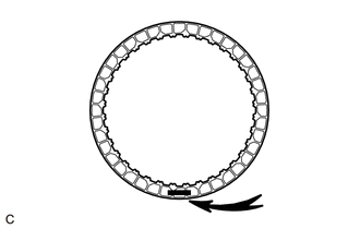
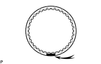
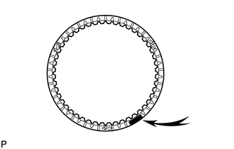
INSPECT NO. 1 ONE-WAY CLUTCH
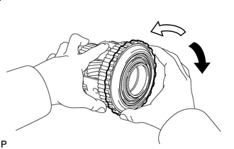

Lock 
Free
-
Install the No. 1 one-way clutch to the rear planetary gear assembly.
-
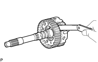
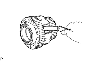
Hold the rear planetary gear assembly and turn the No. 1 one-way clutch.
-
Check that the No. 1 one-way clutch turns freely counterclockwise and locks when turned clockwise.
-
If the No. 1 one-way clutch does not operate normally, replace it.
-
-
-
INSPECT NO. 2 BRAKE DISC
-
Check if the contact surfaces of the No. 2 brake discs, No. 2 brake plates No. 2 brake flange and the brake plate are worn or burnt.
If necessary, replace them.
Note
-
If the lining of any No. 2 brake disc is peeled or discolored, or even if part of the printed number is damaged, replace all the No. 2 brake discs.
-
Before installing new No. 2 brake discs, soak them in ATF for at least 2 hours.
-
-
-
INSPECT NO. 2 CLUTCH DISC
-
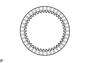
Check if the contact surfaces of the No. 2 clutch discs, No. 2 clutch plates and the No. 2 clutch flange are worn or burnt.
If necessary, replace them.
Note
Before installing new No. 2 clutch discs, soak them in ATF for at least 2 hours.
-
-
INSPECT DIRECT CLUTCH RETURN SPRING SUB-ASSEMBLY
-
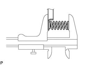
Using a vernier caliper, measure the free length of the direct clutch return spring sub-assembly including the spring seat.
Standard Free Length 20.76 mm (0.817 in.)
-
If the free length is not as specified, replace the direct clutch return spring sub-assembly.
-
-
-
INSPECT PACK CLEARANCE OF NO. 2 BRAKE
-
Using a vernier caliper, measure the distance (Dimension (A)) between the end of the No. 2 brake piston and the point on the automatic transmission case sub-assembly shown in the illustration at several points, and calculate the average.
Tech Tips
Dimension (A) = 14.77 to 15.37 mm (0.581 to 0.605 in.)
-
*a Weight *1 No. 2 Brake Flange *2 No. 2 Brake Plate *3 No. 2 Brake Disc Using a vernier caliper, measure the thickness (Dimension (B)) of the 4 No. 2 brake discs, 3 No. 2 brake plates and No. 2 brake flange when assembled, with a weight (500 g or less) placed on the No. 2 brake flange as shown in the illustration.
Tech Tips
-
Dimension (B) = 13.16 to 14.76 mm (0.518 to 0.581 in.)
-
Standard Clearance = Dimension (A) - Dimension (B)
Standard Clearance 0.52 to 0.82 mm (0.0205 to 0.0323 in.) -
-
If the clearance is not as specified, select and install an appropriate No. 2 brake flange that will bring the clearance within the specified range.
Tech Tips
There are 9 No. 2 brake flanges of different thicknesses.
No. 2 Brake Flange Thickness Part No. Mark Thickness 35678-50010 0 1.95 to 2.05 mm (0.0768 to 0.0807 in.) 35678-50020 1 2.05 to 2.15 mm (0.0807 to 0.0846 in.) 35678-50030 2 2.15 to 2.25 mm (0.0846 to 0.0886 in.) 35678-50040 3 2.25 to 2.35 mm (0.0886 to 0.0925 in.) 35678-50050 4 2.35 to 2.45 mm (0.0925 to 0.0965 in.) 35678-50060 5 2.45 to 2.55 mm (0.0965 to 0.100 in.) 35678-50070 6 2.55 to 2.65 mm (0.100 to 0.104 in.) 35678-50080 7 2.65 to 2.75 mm (0.104 to 0.108 in.) 35678-50090 8 2.75 to 2.85 mm (0.108 to 0.112 in.)
-
-
INSPECT PACK CLEARANCE OF NO. 2 CLUTCH
-
*a Oil Hole Using a dial indicator, measure clearance (Dimension (A)) of the No. 2 clutch while applying compressed air (196 kPa, 2.0 kgf/cm2, 28 psi) to the oil hole as shown in the illustration, and calculate the average.
Standard Clearance 0.90 to 1.20 mm (0.0354 to 0.0472 in.) If the clearance is not as specified, select and install an appropriate No. 2 clutch flange that will bring the clearance within the specified range.
Tech Tips
There are 9 No. 2 clutch flanges of different thicknesses.
No. 2 Clutch Flange Thickness Part No. Mark Thickness 35635-50181 40 3.95 to 4.05 mm (0.156 to 0.159 in.) 35635-50191 41 4.05 to 4.15 mm (0.159 to 0.163 in.) 35635-50201 42 4.15 to 4.25 mm (0.163 to 0.167 in.) 35635-50211 43 4.25 to 4.35 mm (0.167 to 0.171 in.) 35635-50221 44 4.35 to 4.45 mm (0.171 to 0.175 in.) 35635-50231 45 4.45 to 4.55 mm (0.175 to 0.179 in.) 35635-50241 46 4.55 to 4.65 mm (0.179 to 0.183 in.) 35635-50251 47 4.65 to 4.75 mm (0.183 to 0.187 in.) 35635-50261 48 4.75 to 4.85 mm (0.187 to 0.191 in.)
-
-
INSPECT 2ND BRAKE PISTON RETURN SPRING SUB-ASSEMBLY
-
Using a vernier caliper, measure the free length of the 2nd brake piston return spring sub-assembly including the spring seat.
Standard Free Length 23.36 mm (0.920 in.)
-
If the free length is not as specified, replace the 2nd brake piston return spring sub-assembly.
-
-
-
INSPECT INDIVIDUAL PISTON OPERATION
-
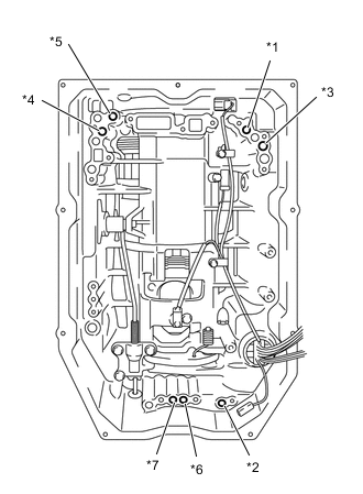
*1 Forward Multiple Clutch *2 No. 2 Clutch *3 No. 3 Clutch *4 Reverse Clutch *5 No. 1 Brake *6 No. 2 Brake (In) *7 No. 2 Brake (Out) Check the operating sound of each piston while applying compressed air to each oil hole shown in the illustration.
-
-
INSPECT AUTOMATIC TRANSMISSION CASE SUB-ASSEMBLY
-
Using a caliper gauge, measure the inside diameter of the automatic transmission case sleeve bushing.
Standard Free Length 49.070 to 49.155 mm (1.93 to 1.94 in.)
-
If the inside diameter is not as specified, replace the automatic transmission case sub-assembly.
-
-