AUTOMATIC TRANSMISSION UNIT(for 8AR-FTS) INSPECTION

PROCEDURE
-
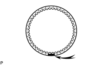
INSPECT NO. 1 BRAKE DISC
-
Check if the contact surfaces of the No. 1 brake discs, No. 1 brake plates and the No. 1 brake flange are worn or burnt.
Note
-
If the lining of any No. 1 brake disc is peeled or discolored, or even if part of the printed number is damaged, replace all the No. 1 brake discs.
-
Before installing new No. 1 brake discs, soak them in ATF for at least 2 hours.
If necessary, replace them.
-
-
-
INSPECT FRONT PLANETARY GEAR ASSEMBLY
-
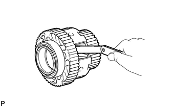
Using a feeler gauge, measure the clearance between the front planetary gear assembly and each pinion gear.
Standard Clearance 0.2 to 0.6 mm (0.00788 to 0.0236 in.) If the clearance is not as specified, replace the front planetary gear assembly.
-
-
INSPECT PACK CLEARANCE OF NO. 1 BRAKE
-
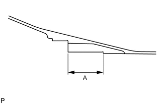
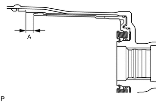
Using a vernier caliper, measure the distance (Dimension (A)) between the installation surface of the oil pump assembly and the installation surface the No. 1 brake flange shown in the illustration at several points, and calculate the average.
Tech Tips
Dimension (A) = 59.77 to 60.03 mm (2.354 to 2.363 in.)
-
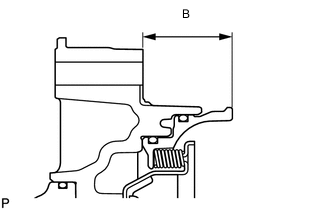
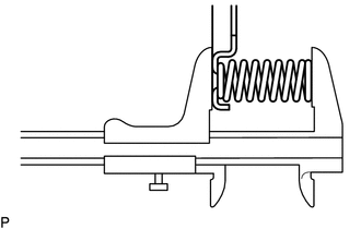
Using a vernier caliper, measure the distance (Dimension (B)) between the front of the oil pump assembly and the front of the No. 1 brake piston shown in the illustration at several points, and calculate the average.
Tech Tips
Dimension (B) = 38.17 to 38.49 mm (1.503 to 1.515 in.)
-
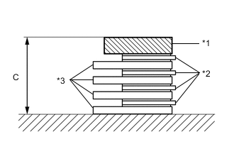
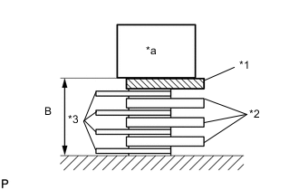
*1 No. 1 Brake Flange *2 No. 1 Brake Disc *3 No. 1 Brake Plate Using a vernier caliper, measure the thickness (Dimension (C)) of the 4 No. 1 brake plates, 4 No. 1 brake discs, and No. 1 brake flange, when assembled.
Tech Tips
-
Dimension (C) = 20.31 to 20.73 mm (0.800 to 0.816 in.)
-
Standard Clearance = Dimension (A) - Dimension (B) - Dimension (C)
Standard Clearance 0.40 to 0.70 mm (0.0158 to 0.0275 in.) -
-
If the clearance is not as specified, select and install a No. 1 brake flange that will bring the clearance within the specified range.
Tech Tips
There are 9 No. 1 brake flanges of different thickness.
No. 1 Brake Flange Thickness Part No. Mark Thickness 35676-50070 0 4.45 to 4.55 mm (0.176 to 0.179 in.) 35676-50080 1 4.55 to 4.65 mm (0.180 to 0.183 in.) 35676-50090 2 4.65 to 4.75 mm (0.184 to 0.187 in.) 35676-50100 3 4.75 to 4.85 mm (0.188 to 0.190 in.) 35676-50110 4 4.85 to 4.95 mm (0.191 to 0.194 in.) 35676-50120 5 4.95 to 5.05 mm (0.195 to 0.198 in.) 35676-50130 6 5.05 to 5.15 mm (0.199 to 0.202 in.) 35676-50140 7 5.15 to 5.25 mm (0.203 to 0.206 in.) 35676-50150 8 5.25 to 5.35 mm (0.207 to 0.210 in.)
-
-
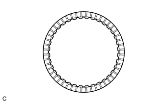
INSPECT NO. 3 CLUTCH DISC
-
Check if the contact surfaces of the No. 3 clutch discs, No. 3 clutch plates and the No. 3 clutch flange are worn or burnt.
Note
Before installing new No. 3 clutch discs, soak them in ATF for at least 2 hours.
If necessary, replace them.
-
-
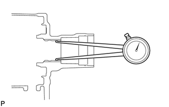
INSPECT PACK CLEARANCE OF NO. 3 CLUTCH
-
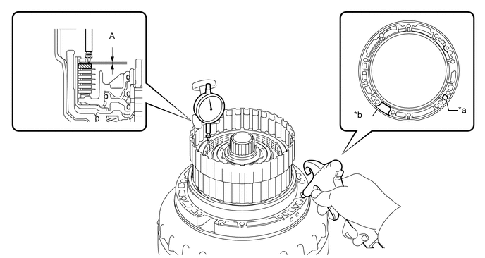
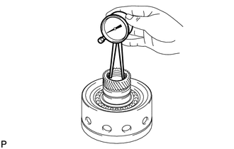
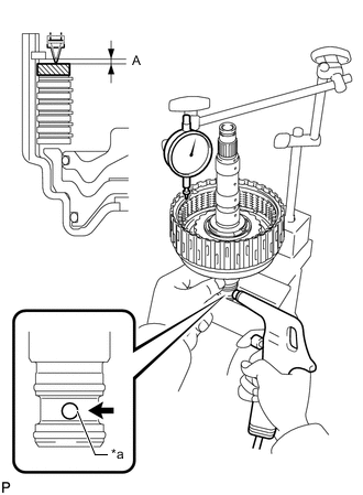
Using a dial indicator, measure the clearance (Dimension (A)) of the No. 3 clutch at several points while applying compressed air (196 kPa, 2.0 kgf/cm2, 28 psi) to the oil hole as shown in the illustration, and calculate the average.
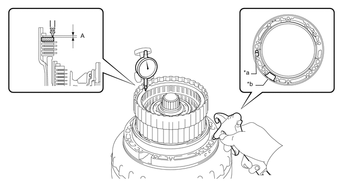
*a Oil Hole *b Speed Sensor Hole Standard Clearance 0.4 to 0.7 mm (0.0158 to 0.0275 in.) If the clearance is not as specified, select and install an appropriate No. 3 clutch flange that will bring the clearance within the specified range.
Tech Tips
There are 7 No. 3 clutch flanges of different thicknesses.
No. 3 Clutch Flange Thickness Part No. Mark Thickness 34615-50060 0 3.95 to 4.05 mm (0.156 to 0.159 in.) 34615-50070 1 4.05 to 4.15 mm (0.160 to 0.163 in.) 34615-50080 2 4.15 to 4.25 mm (0.164 to 0.167 in.) 34615-50090 3 4.25 to 4.35 mm (0.168 to 0.171 in.) 34615-50100 4 4.35 to 4.45 mm (0.172 to 0.175 in.) 34615-50110 5 4.45 to 4.55 mm (0.176 to 0.179 in.) 34615-50120 6 4.55 to 4.65 mm (0.180 to 0.183 in.)
-
-
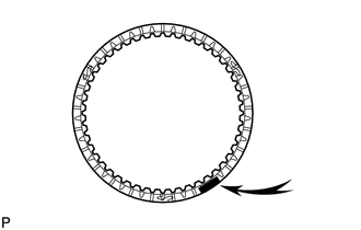
INSPECT REVERSE CLUTCH DISC
-
Check if the contact surfaces of the reverse clutch discs, reverse clutch plates and the reverse clutch flange are worn or burnt.
Note
-
If the lining of any reverse clutch disc is peeled or discolored, or even if part of the printed number is damaged, replace all the reverse clutch discs.
-
Before installing new reverse clutch discs, soak them in ATF for at least 2 hours.
If necessary, replace them.
-
-
-
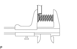
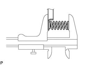
INSPECT REVERSE CLUTCH RETURN SPRING SUB-ASSEMBLY
-
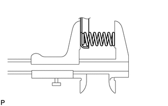
Using a vernier caliper, measure the free length of the reverse clutch return spring sub-assembly including the spring seat.
Standard Free Length 22.21 mm (0.874 in.) If the free length is not as specified, replace the reverse clutch return spring sub-assembly.
-
-
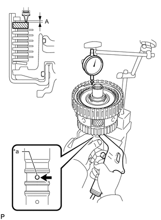
INSPECT PACK CLEARANCE OF REVERSE CLUTCH
-
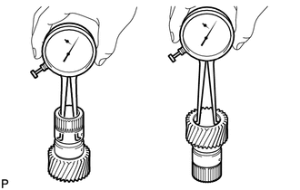
Using a dial indicator, measure the clearance (Dimension (A)) of the reverse clutch at several points while applying compressed air (196 kPa, 2.0 kgf/cm2, 28 psi) to the oil hole as shown in the illustration, and calculate the average.
*a Oil Hole *b Speed Sensor Hole Standard Clearance 0.5 to 0.8 mm (0.0197 to 0.0314 in.) If the clearance is not as specified, select and install an appropriate reverse clutch flange that will bring the clearance within the specified range.
Tech Tips
There are 9 reverse clutch flanges of different thicknesses.
Reverse Clutch Flange Thickness Part No. Mark Thickness 35649-50080 0 2.95 to 3.05 mm (0.117 to 0.120 in.) 35649-50090 1 3.05 to 3.15 mm (0.121 to 0.124 in.) 35649-50100 2 3.15 to 3.25 mm (0.125 to 0.127 in.) 35649-50110 3 3.25 to 3.35 mm (0.128 to 0.131 in.) 35649-50120 4 3.35 to 3.45 mm (0.132 to 0.135 in.) 35649-50130 5 3.45 to 3.55 mm (0.136 to 0.139 in.) 35649-50140 6 3.55 to 3.65 mm (0.140 to 0.143 in.) 35649-50150 7 3.65 to 3.75 mm (0.144 to 0.147 in.) 35649-50160 8 3.75 to 3.85 mm (0.148 to 0.151 in.)
-
-
INSPECT OVERDRIVE CLUTCH RETURN SPRING SUB-ASSEMBLY
-
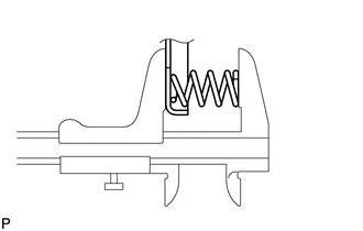
Using a vernier caliper, measure the free length of the overdrive clutch return spring sub-assembly including the spring seat.
Standard Free Length 21.09 mm (0.830 in.) If the free length is not as specified, replace the overdrive clutch return spring sub-assembly.
-
-
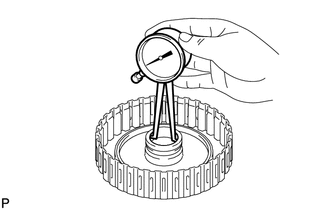
INSPECT OVERDRIVE DIRECT CLUTCH DRUM SUB-ASSEMBLY
-
Using a caliper gauge, measure the inside diameter of the overdrive direct clutch drum sub-assembly bushing.
Standard Inside Diameter (Front Side) 67.40 to 67.44 mm (2.654 to 2.655 in.) Standard Inside Diameter (Rear Side) 55.62 to 55.64 mm (2.1898 to 2.1905 in.) If the inside diameter is not as specified, replace the overdrive direct clutch drum sub-assembly.
-
-
INSPECT FORWARD MULTIPLE CLUTCH DISC
-
Check if the contact surfaces of the forward multiple clutch discs, forward multiple clutch plates, forward clutch flange and the clutch cushion plate are worn or burnt.
Note
-
If the lining of any forward multiple clutch disc is peeled or discolored, or even if part of the printed number is damaged, replace all the forward multiple clutch discs.
-
Before installing new forward multiple clutch discs, soak them in ATF for at least 2 hours.
If necessary, replace them.
-
-
-
INSPECT FORWARD CLUTCH RETURN SPRING SUB-ASSEMBLY
-
Using a vernier caliper, measure the free length of the forward clutch return spring sub-assembly including the spring seat.
Standard Free Length 20.82 mm (0.820 in.) If the free length is not as specified, replace the forward clutch return spring sub-assembly.
-
-
INSPECT PACK CLEARANCE OF FORWARD MULTIPLE CLUTCH
-
Temporarily install the front planetary gear assembly to the forward clutch drum sub-assembly.
-
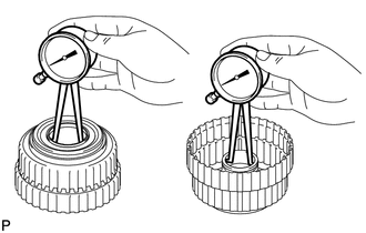
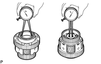
*a Oil Hole Using a dial indicator, measure the clearance (Dimension (A)) of the forward multiple clutch at multiple points while applying compressed air (196 kPa, 2.0 kgf/cm2, 28 psi) to the oil hole as shown in the illustration, and calculate the average.
Standard Clearance 0.90 to 1.20 mm (0.0355 to 0.0472 in.) -
If the clearance is not as specified, select and install an appropriate forward clutch flange that will bring the pack clearance within the standard range.
Tech Tips
There are 9 forward clutch flanges of different thicknesses.
Forward Clutch Flange Thickness Part No. Mark Thickness 35635-50090 0 4.35 to 4.45 mm (0.172 to 0.175 in.) 35635-50100 1 4.45 to 4.55 mm (0.176 to 0.179 in.) 35635-50110 2 4.55 to 4.65 mm (0.180 to 0.183 in.) 35635-50120 3 4.65 to 4.75 mm (0.184 to 0.187 in.) 35635-50130 4 4.75 to 4.85 mm (0.188 to 0.190 in.) 35635-50140 5 4.85 to 4.95 mm (0.191 to 0.194 in.) 35635-50150 6 4.95 to 5.05 mm (0.195 to 0.198 in.) 35635-50160 7 5.05 to 5.15 mm (0.199 to 0.202 in.) 35635-50170 8 5.15 to 5.25 mm (0.203 to 0.206 in.) -
Remove the front planetary gear assembly from the forward clutch drum sub-assembly.
-
-
INSPECT FORWARD CLUTCH DRUM SUB-ASSEMBLY
-
Using a caliper gauge, measure the inside diameter of the forward clutch drum sub-assembly bushing.
Standard Inside Diameter 33.200 to 33.225 mm (1.3071 to 1.3080 in.) If the inside diameter is not as specified, replace the forward clutch drum sub-assembly.
-
-
INSPECT SUN GEAR INPUT DRUM SUB-ASSEMBLY
-
Using a caliper gauge, measure the inside diameter of the sun gear input drum sub-assembly bushing.
Standard Inside Diameter 45.075 to 45.100 mm (1.7747 to 1.7755 in.) If the inside diameter is not as specified, replace the sun gear input drum sub-assembly.
-
-
INSPECT REAR PLANETARY SUN GEAR SUB-ASSEMBLY
-
Using a caliper gauge, measure the inside diameter of the rear planetary sun gear sub-assembly bushing.
Standard Inside Diameter 28.700 to 28.721 mm (1.1300 to 1.1307 in.) If the inside diameter is not as specified, replace the rear planetary sun gear sub-assembly.
-
-
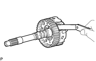
INSPECT REAR PLANETARY GEAR ASSEMBLY
-
Using a feeler gauge, measure the clearance between the rear planetary gear assembly and each pinion gear long and short thrust clearance.
Standard Clearance 0.2 to 0.6 mm (0.00788 to 0.0236 in.) If the clearance is not as specified, replace the rear planetary gear assembly.
-
Using a caliper gauge, measure the inside diameter of the rear planetary gear assembly bushing.
Standard Inside Diameter (Front Side) 71.60 to 71.63 mm (2.819 to 2.820 in.) Standard Inside Diameter (Rear Side) 28.700 to 28.721 mm (1.1300 to 1.1307 in.) If the inside diameter is not as specified, replace the rear planetary gear assembly.
-
-
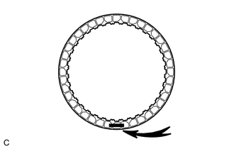
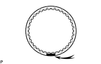
INSPECT NO. 1 ONE-WAY CLUTCH
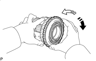

Lock 
Free
-
Install the No. 1 one-way clutch to the rear planetary gear assembly.
-
Hold the rear planetary gear assembly and turn the No. 1 one-way clutch.
-
Check that the No. 1 one-way clutch turns freely counterclockwise and locks when turned clockwise.
If the No. 1 one-way clutch does not operate normally, replace it.
-
-
INSPECT NO. 2 BRAKE DISC
-
Check if the contact surfaces of the No. 2 brake discs, No. 2 brake plates No. 2 brake flange and the brake plate are worn or burnt.
Note
-
If the lining of any No. 2 brake disc is peeled or discolored, or even if part of the printed number is damaged, replace all the No. 2 brake discs.
-
Before installing new No. 2 brake discs, soak them in ATF for at least 2 hours.
If necessary, replace them.
-
-
-
INSPECT NO. 2 CLUTCH DISC
-
Check if the contact surfaces of the No. 2 clutch discs, No. 2 clutch plates and the No. 2 clutch flange are worn or burnt.
Note
Before installing new No. 2 clutch discs, soak them in ATF for at least 2 hours.
If necessary, replace them.
-
-
INSPECT DIRECT CLUTCH RETURN SPRING SUB-ASSEMBLY
-
Using a vernier caliper, measure the free length of the direct clutch return spring sub-assembly including the spring seat.
Standard Free Length 20.76 mm (0.817 in.) If the free length is not as specified, replace the direct clutch return spring sub-assembly.
-
-
INSPECT PACK CLEARANCE OF NO. 2 BRAKE
-
Using a vernier caliper, measure the distance (Dimension (A)) between the end of the No. 2 brake piston and the point on the automatic transmission case sub-assembly shown in the illustration at several points, and calculate the average.
Tech Tips
Dimension (A) = 14.77 to 15.37 mm (0.582 to 0.605 in.)
-
*a Weight *1 No. 2 Brake Flange *2 No. 2 Brake Plate *3 No. 2 Brake Disc Using a vernier caliper, measure the thickness (Dimension (B)) of the 4 No. 2 brake discs, 3 No. 2 brake plates and No. 2 brake flange when assembled, with a weight (500 g or less) placed on the No. 2 brake flange as shown in the illustration.
Tech Tips
-
Dimension (B) = 14.11 to 14.69 mm (0.556 to 0.578 in.)
-
Standard Clearance = Dimension (A) - Dimension (B)
Standard Clearance 0.40 to 0.70 mm (0.0158 to 0.0275 in.) -
-
If the clearance is not as specified, select and install an appropriate No. 2 brake flange that will bring the clearance within the specified range.
Tech Tips
There are 9 No. 2 brake flanges of different thicknesses.
No. 2 Brake Flange Thickness Part No. Mark Thickness 35678-50010 0 1.95 to 2.05 mm (0.0768 to 0.0807 in.) 35678-50020 1 2.05 to 2.15 mm (0.0808 to 0.0846 in.) 35678-50030 2 2.15 to 2.25 mm (0.0847 to 0.0885 in.) 35678-50040 3 2.25 to 2.35 mm (0.0886 to 0.0925 in.) 35678-50050 4 2.35 to 2.45 mm (0.0926 to 0.0964 in.) 35678-50060 5 2.45 to 2.55 mm (0.0965 to 0.100 in.) 35678-50070 6 2.55 to 2.65 mm (0.101 to 0.104 in.) 35678-50080 7 2.65 to 2.75 mm (0.105 to 0.108 in.) 35678-50090 8 2.75 to 2.85 mm (0.109 to 0.112 in.)
-
-
INSPECT PACK CLEARANCE OF NO. 2 CLUTCH
-
*a Oil Hole Using a dial indicator, measure clearance (Dimension (A)) of the No. 2 clutch while applying compressed air (196 kPa, 2.0 kgf/cm2, 28 psi) to the oil hole as shown in the illustration, and calculate the average.
Standard Clearance 0.90 to 1.20 mm (0.0355 to 0.0472 in.) If the clearance is not as specified, select and install an appropriate No. 2 clutch flange that will bring the clearance within the specified range.
Tech Tips
There are 9 No. 2 clutch flanges of different thicknesses.
No. 2 Clutch Flange Thickness Part No. Mark Thickness 35635-50181 40 3.95 to 4.05 mm (0.156 to 0.159 in.) 35635-50191 41 4.05 to 4.15 mm (0.160 to 0.163 in.) 35635-50201 42 4.15 to 4.25 mm (0.164 to 0.167 in.) 35635-50211 43 4.25 to 4.35 mm (0.168 to 0.171 in.) 35635-50221 44 4.35 to 4.45 mm (0.172 to 0.175 in.) 35635-50231 45 4.45 to 4.55 mm (0.176 to 0.179 in.) 35635-50241 46 4.55 to 4.65 mm (0.180 to 0.183 in.) 35635-50251 47 4.65 to 4.75 mm (0.184 to 0.187 in.) 35635-50261 48 4.75 to 4.85 mm (0.188 to 0.190 in.)
-
-
INSPECT 2ND BRAKE PISTON RETURN SPRING SUB-ASSEMBLY
-
Using a vernier caliper, measure the free length of the 2nd brake piston return spring sub-assembly including the spring seat.
Standard Free Length 22.16 mm (0.872 in.) If the free length is not as specified, replace the 2nd brake piston return spring sub-assembly.
-
-
INSPECT INDIVIDUAL PISTON OPERATION
-
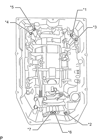
*1 Forward Multiple Clutch *2 No. 2 Clutch *3 No. 3 Clutch *4 Reverse Clutch *5 No. 1 Brake *6 No. 2 Brake (In) *7 No. 2 Brake (Out) Check the operating sound of each piston while applying compressed air to each oil hole shown in the illustration.
-
-
INSPECT AUTOMATIC TRANSMISSION CASE SUB-ASSEMBLY
-
Using a caliper gauge, measure the inside diameter of the automatic transmission case sub-assembly sleeve bushing.
Standard Free Length 49.070 to 49.155 mm (1.932 to 1.935 in.) If the inside diameter is not as specified, replace the automatic transmission case sub-assembly.
-