VALVE BODY ASSEMBLY(for 8AR-FTS) INSTALLATION
PROCEDURE
-
INSTALL TRANSMISSION VALVE BODY ASSEMBLY
-
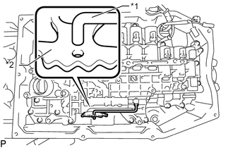
*1 Manual Valve Connecting Rod *2 Manual Valve Lever Sub-assembly Install the transmission valve body assembly and connect the manual valve connecting rod to the manual valve lever sub-assembly.
-
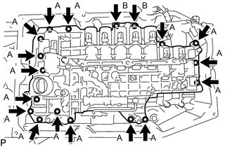
Install the 18 bolts to the transmission valve body assembly.
- Torque:
- 11 N*m { 112 kgf*cm, 8 ft.*lbf }
Tech Tips
-
Bolt (A): 31 mm (1.22 in.)
-
Bolt (B): 21 mm (0.827 in.)
Bolt Length
-
Install the detent spring and detent spring cover with the bolt.
- Torque:
- 10 N*m { 102 kgf*cm, 7 ft.*lbf }
-
w/ Stop and Start System:
-
Connect the 10 connectors.
-
Coat the O-ring of the ATF temperature sensor with ATF.
-
Connect the ATF temperature sensor and install the lock plate with the bolt.
- Torque:
- 10 N*m { 102 kgf*cm, 7 ft.*lbf }
Note
-
When reusing the ATF temperature sensor, inspect the O-ring.
-
Make sure that the O-ring is not cracked or jammed when installing the transmission wire.
-
-
w/o Stop and Start System:
-
Connect the 9 connectors.
-
Coat the O-ring of the ATF temperature sensor with ATF.
-
Connect the ATF temperature sensor and install the lock plate with the bolt.
- Torque:
- 10 N*m { 102 kgf*cm, 7 ft.*lbf }
Note
-
When reusing the ATF temperature sensor, inspect the O-ring.
-
Make sure that the O-ring is not cracked or jammed when installing the transmission wire.
-
-
-
INSTALL VALVE BODY OIL STRAINER ASSEMBLY
-
Coat a new O-ring with ATF and install it to the valve body oil strainer assembly.
Note
Ensure that the O-ring is not twisted or pinched.
-
Install the valve body oil strainer assembly to the transmission valve body assembly with the 4 bolts.
- Torque:
- 10 N*m { 102 kgf*cm, 7 ft.*lbf }
-
-
INSTALL AUTOMATIC TRANSMISSION OIL PAN SUB-ASSEMBLY
-
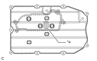
*a Inlet Port 
Valve Body Oil Strainer Assembly Position 
Transmission Oil Cleaner Magnet Install the 6 transmission oil cleaner magnets to the automatic transmission oil pan sub-assembly as shown in the illustration.
Note
Make sure to install the transmission oil cleaner magnets so that they do not contact the inlet port of the valve body oil strainer assembly when the automatic transmission oil pan sub-assembly is installed.
-
Install a new automatic transmission oil pan gasket to the automatic transmission oil pan sub-assembly.
-
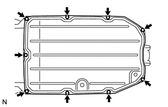
Install the automatic transmission oil pan sub-assembly with automatic transmission oil pan gasket to the automatic transmission case sub-assembly with the 9 bolts.
- Torque:
- 7.4 N*m { 75 kgf*cm, 65 in.*lbf }
Note
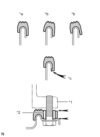
*1 Automatic Transmission Case Sub-assembly *2 Sleeve *a Correct *b Incorrect *c Protrusion
-
Make sure that automatic transmission oil pan gasket seal surface and automatic transmission oil pan sub-assembly contact surface are free of oil and foreign matter.
-
Install the automatic transmission oil pan gasket so that there is no slack in the automatic transmission oil pan gasket, and the entire seal surface is level.
-
Make sure that the 9 protrusions are properly engaged to the automatic transmission oil pan sub-assembly.
-
When installing the automatic transmission oil pan sub-assembly, make sure that the automatic transmission oil pan gasket is not pinched between a sleeve and the seal surface of the automatic transmission case sub-assembly.
-
-
INSTALL NO. 2 ENGINE UNDER COVER (w/ No. 2 Engine Under Cover)
-
INSTALL FRONT SUSPENSION MEMBER BRACE
-
ADD AUTOMATIC TRANSMISSION FLUID
-
RESET MEMORY