AUTOMATIC TRANSMISSION SYSTEM(for 2GR-FKS), Diagnostic DTC:P070312
| DTC Code | DTC Name |
|---|---|
| P070312 | Brake Switch "B" Circuit Short to Battery |
DESCRIPTION
The purpose of this circuit is to prevent the engine from stalling when the brakes are suddenly applied while driving in the lock-up condition.
When the brake pedal is depressed, the stop light switch assembly sends a signal to the ECM. The ECM then cancels the operation of the lock-up clutch while braking is in progress.
| DTC No. | Detection Item | DTC Detection Condition | Trouble Area | MIL | Memory | Note |
|---|---|---|---|---|---|---|
| P070312 | Brake Switch "B" Circuit Short to Battery | All of the following conditions are met (2-trip detection logic):
|
|
Comes on | DTC stored | SAE Code: P0724 |
MONITOR DESCRIPTION
This DTC indicates that the stop light switch assembly is remaining on. When the stop light switch assembly remains on during GO and STOP driving, the ECM interprets this as a malfunction of the stop light switch circuit, then illuminates the MIL and stores this DTC. The vehicle must GO (30 km/h (19 mph) or more) and STOP (less than 3 km/h (2 mph)) 5 times for 2 driving cycles in order for the DTC to be output.
CONFIRMATION DRIVING PATTERN
CAUTION:
When performing the confirmation driving pattern, obey all speed limits and traffic laws.
Tech Tips
After repairs have been completed, clear the DTCs and then check that the vehicle has returned to normal by performing the following All Readiness check procedure.
-
Connect the GTS to the DLC3.
-
Turn the engine switch on (IG) and turn the GTS on.
-
Clear the DTCs (even if no DTCs are stored, perform the clear DTC procedure).
-
Turn the engine switch off and wait for 2 minutes or more.
-
Turn the engine switch on (IG) and turn the GTS on.
-
Start the engine.
-
Repeat the following procedure 5 times:
-
Accelerate the vehicle to 30 km/h (19 mph) or more, depress the brake pedal and decelerate the vehicle to 3 km/h (2 mph) or less.
-
Stop the vehicle.
-
Enter the following menus: Powertrain / Transmission / Utility / All Readiness.
-
Input the DTC: P070312.
-
Check the DTC judgment result.
GTS Display Description NORMAL
-
DTC judgment completed
-
System normal
ABNORMAL
-
DTC judgment completed
-
System abnormal
INCOMPLETE
-
DTC judgment not completed
-
Perform driving pattern after confirming DTC enabling conditions
N/A
-
Unable to perform DTC judgment
-
Number of DTCs which do not fulfill DTC preconditions has reached ECU memory limit
Tech Tips
-
If the judgment result shows NORMAL, the system is normal.
-
If the judgment result shows ABNORMAL, the system has a malfunction.
-
If the judgment result shows INCOMPLETE or N/A, perform the Confirmation Driving Pattern and check the DTC judgment result again.
-
WIRING DIAGRAM
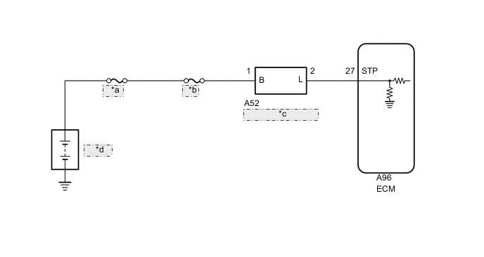
| *a | ENG-B |
| *b | STOP |
| *c | Stop Light Switch Assembly |
| *d | Battery |
CAUTION / NOTICE / HINT
Note
-
Inspect the fuses for circuits related to this system before performing the following procedure.
-
Perform registration and/or initialization when parts related to the automatic transmission are replaced.
PROCEDURE
-
READ VALUE USING GTS (STOP LIGHT SW)
-
Turn the engine switch off.
-
Connect the GTS to the DLC3.
-
Turn the engine switch on (IG).
-
Turn the GTS on.
-
Enter the following menus: Powertrain / Transmission / Data List / Stop Light SW.
-
Read the Data List according to the display on the GTS.
Powertrain > Transmission > Data ListTester Display Measurement Item Range Normal Condition Diagnostic Note Stop Light SW Stop light switch assembly status ON or OFF
-
ON: Brake pedal depressed
-
OFF: Brake pedal released
-
Powertrain > Transmission > Data ListTester Display Stop Light SW Result Result Proceed to Data List value is normal A Data List value is not normal B -
A 
CHECK FOR INTERMITTENT PROBLEMS Click here
B 
-
-
CHECK STOP LIGHT SWITCH ASSEMBLY INSTALLATION
-
Check the stop light switch assembly installation.
OK Stop light switch assembly is installed correctly. Result Proceed to OK NG
NG
SECURELY REINSTALL STOP LIGHT SWITCH ASSEMBLY Click here
OK
-
-
INSPECT STOP LIGHT SWITCH ASSEMBLY
-
Inspect the stop light switch assembly.
Result Proceed to OK NG
NG
REPAIR OR REPLACE HARNESS OR CONNECTOR
OK
-
-
CHECK TERMINAL VOLTAGE (STP VOLTAGE)
-
Disconnect the A96 ECM connector.
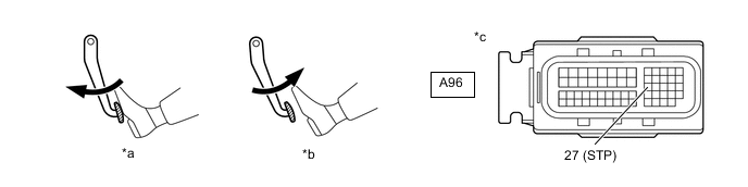
*a Brake pedal depressed *b Brake pedal released *c Front view of wire harness connector
(to ECM)
- - -
Measure the voltage according to the value(s) in the table below.
Standard Voltage Tester Connection Condition Specified Condition A96-27 (STP) - Body ground Brake pedal released Below 1.5 V Brake pedal depressed 7.5 to 14 V Tech Tips
If there is a short in the STP terminal circuit, there may be a malfunction in the circuit of a connected ECU.
Result Proceed to OK NG
NG
REPLACE STOP LIGHT SWITCH ASSEMBLY Click here
OK
-
-
REPLACE ECM
-
Replace the ECM.
Result Proceed to NEXT
NEXT
PERFORM A/T CODE REGISTRATION Click here
-