AUTOMATIC TRANSMISSION SYSTEM(for 2GR-FKS), Diagnostic DTC:P072012, P072014, P072031
| DTC Code | DTC Name |
|---|---|
| P072012 | Output Speed Sensor Circuit Short to Battery |
| P072014 | Output Speed Sensor Circuit Short to Ground or Open |
| P072031 | Output Speed Sensor No Signal |
DESCRIPTION
The transmission revolution sensor (SP2) detects the output shaft rotation speed and sends it to the ECM.
Based on the transmission revolution sensor (NT) signal and the transmission revolution sensor (SP2) signal, the ECM controls engine torque and shift timing.
| DTC No. | Detection Item | DTC Detection Condition | Trouble Area | MIL | Memory | Note |
|---|---|---|---|---|---|---|
| P072012 | Output Speed Sensor Circuit Short to Battery | All of the following conditions are met (1-trip detection logic):
|
|
Comes on | DTC stored | SAE Code: P077D |
| P072014 | Output Speed Sensor Circuit Short to Ground or Open | All of the following conditions are met (1-trip detection logic):
|
|
Comes on | DTC stored | SAE Code: P077C |
| P072031 | Output Speed Sensor No Signal | All of the following conditions are met (1-trip detection logic):
|
|
Comes on | DTC stored | SAE Code: P0722 |
MONITOR DESCRIPTION
The transmission revolution sensor (SP2) monitors the output shaft speed.
The ECM controls the gearshift point and the lock-up timing based on the signals from the transmission revolution sensor (SP2) and throttle position sensor.
If the ECM detects no signal from the transmission revolution sensor (SP2) even while the vehicle is moving, it will determine the transmission revolution sensor (SP2) is malfunctioning, illuminate the MIL and store a DTC.
CONFIRMATION DRIVING PATTERN
CAUTION:
When performing the confirmation driving pattern, obey all speed limits and traffic laws.
Tech Tips
After repairs have been completed, clear the DTCs and then check that the vehicle has returned to normal by performing the following All Readiness check procedure.
-
Connect the GTS to the DLC3.
-
Turn the engine switch on (IG) and turn the GTS on.
-
Clear the DTCs (even if no DTCs are stored, perform the clear DTC procedure).
-
Turn the engine switch off and wait for 2 minutes or more.
-
Turn the engine switch on (IG) and turn the GTS on.
-
Start the engine.
-
Perform the D Position Shift Test inspection in Road Test.
-
Stop the vehicle.
-
Enter the following menus: Powertrain / Transmission / Utility / All Readiness.
-
Input the DTC: P072012, P072014 or P072031.
-
Check the DTC judgment result.
GTS Display Description NORMAL
-
DTC judgment completed
-
System normal
ABNORMAL
-
DTC judgment completed
-
System abnormal
INCOMPLETE
-
DTC judgment not completed
-
Perform driving pattern after confirming DTC enabling conditions
N/A
-
Unable to perform DTC judgment
-
Number of DTCs which do not fulfill DTC preconditions has reached ECU memory limit
Tech Tips
-
If the judgment result shows NORMAL, the system is normal.
-
If the judgment result shows ABNORMAL, the system has a malfunction.
-
If the judgment result shows INCOMPLETE or N/A, perform the Confirmation Driving Pattern and check the DTC judgment result again.
-
WIRING DIAGRAM
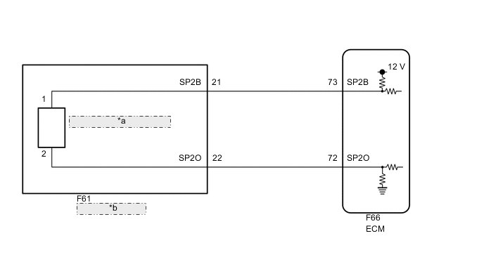
| *a | Transmission Revolution Sensor (SP2) |
| *b | Transmission Wire |
CAUTION / NOTICE / HINT
Note
Perform registration and/or initialization when parts related to the automatic transmission are replaced.
-
DATA LIST
Note
In the table below, the values listed under "Normal Condition" are reference values. Do not depend solely on these reference values when deciding whether a part is faulty or not.
Tech Tips
Using the GTS to read the Data List allows the values or states of switches, sensors, actuators and other items to be read without removing any parts. This non-intrusive inspection can be very useful because intermittent conditions or signals may be discovered before parts or wiring is disturbed. Reading the Data List information early in troubleshooting is one way to save diagnostic time.
-
Warm up the engine.
-
Turn the engine switch off.
-
Connect the GTS to the DLC3.
-
Turn the engine switch on (IG).
-
Turn the GTS on.
-
Enter the following menus: Powertrain / Transmission / Data List.
-
Read the Data List according to the display on the GTS.
Powertrain > Transmission > Data ListTester Display Measurement Item Range Normal Condition Diagnostic Note Speed (SP2) Output shaft speed Min.: 0 km/h (0 mph)
Max.: 255 km/h (158 mph)
0 km/h (0 mph): Vehicle stopped (Output shaft speed is equal to vehicle speed) -
Powertrain > Transmission > Data ListTester Display Speed (SP2) Tech Tips
-
Speed (SP2) is always 0 while driving: Open or short in the sensor or circuit.
-
The Speed (SP2) value displayed on the GTS is much lower than the actual vehicle speed: Sensor malfunction, improper installation, or intermittent connection malfunction of the circuit.
-
-
PROCEDURE
-
READ VALUE USING GTS (SPEED (SP2) AND SP2 SENSOR VOLTAGE)
-
Connect the GTS to the DLC3.
-
Turn the engine switch on (IG).
-
Turn the GTS on.
-
Enter the following menus: Powertrain / Transmission / Data List.
-
Read the Data List according to the display on the GTS.
Powertrain > Transmission > Data ListTester Display Measurement Item Range Normal Condition Diagnostic Note Speed (SP2) Output shaft speed Min.: 0 km/h (0 mph)
Max.: 255 km/h (158 mph)
0 km/h (0 mph): Vehicle stopped (Output shaft speed is equal to vehicle speed) - SP2 Sensor Voltage SP2 sensor voltage Min.: 0.000 V
Max.: 4.999 V
0.1 to 1.9 V: Engine idling -
Powertrain > Transmission > Data ListTester Display Speed (SP2) SP2 Sensor Voltage Result Result Proceed to Data List values are normal A Data List values are not normal B
A 
GO TO STEP 5 Click here
B 
-
-
CHECK TRANSMISSION REVOLUTION SENSOR TERMINAL (SP2 TERMINAL)
-
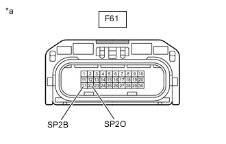
*a Front view of wire harness connector
(to Transmission Wire)
Disconnect the F61 transmission wire connector.
-
Measure the resistance according to the value(s) in the table below.
Standard Resistance Tester Connection Condition Specified Condition F61-22 (SP2O) - Body ground Always 99 to 101 Ω -
Turn the engine switch on (IG).
-
Measure the voltage according to the value(s) in the table below.
Standard Voltage Tester Connection Condition Specified Condition F61-21 (SP2B) - Body ground Engine switch on (IG) 11 to 14 V Result Proceed to OK NG
NG
CHECK HARNESS AND CONNECTOR (TRANSMISSION WIRE - ECM) Click here
OK
-
-
INSPECT TRANSMISSION WIRE (TRANSMISSION REVOLUTION SENSOR (SP2))
-
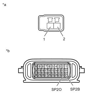
*a Front view of wire harness connector
(to Transmission Revolution Sensor (SP2))
*b Component without harness connected
(Transmission Wire)
Disconnect the transmission revolution sensor (SP2) connector.
-
Disconnect the F61 transmission wire connector.
-
Measure the resistance according to the value(s) in the table below.
Standard Resistance Tester Connection Condition Specified Condition Terminal 1 of the transmission revolution sensor (SP2) connector - 21 (SP2B) Always Below 1 Ω Terminal 2 of the transmission revolution sensor (SP2) connector - 22 (SP2O) Always Below 1 Ω Terminal 1 of the transmission revolution sensor (SP2) connector or 21 (SP2B) - Body ground Always 10 kΩ or higher Terminal 2 of the transmission revolution sensor (SP2) connector or 22 (SP2O) - Body ground Always 10 kΩ or higher Result Proceed to OK NG
OK 
REPLACE TRANSMISSION REVOLUTION SENSOR (SP2) Click here
NG
REPAIR OR REPLACE TRANSMISSION WIRE Click here
-
-
CHECK HARNESS AND CONNECTOR (TRANSMISSION WIRE - ECM)
-
Disconnect the F61 transmission wire connector.
-
Disconnect the F66 ECM connector.
-
Measure the resistance according to the value(s) in the table below.
Standard Resistance Tester Connection Condition Specified Condition F61-21 (SP2B) - F66-73 (SP2B) Always Below 1 Ω F61-22 (SP2O) - F66-72 (SP2O) Always Below 1 Ω F61-21 (SP2B) or F66-73 (SP2B) - Body ground Always 10 kΩ or higher F61-22 (SP2O) or F66-72 (SP2O) - Body ground Always 10 kΩ or higher Result Proceed to OK NG
NG
REPAIR OR REPLACE HARNESS OR CONNECTOR
OK
-
-
REPLACE ECM
-
Replace the ECM.
Result Proceed to NEXT
NEXT
PERFORM A/T CODE REGISTRATION Click here
-