AUTOMATIC TRANSMISSION SYSTEM(for 2GR-FSE) Kick Down Switch Circuit
DESCRIPTION
The kick down switch turns ON when the accelerator pedal is fully depressed to send a signal to the ECM.
When the kick down switch is ON, the ECM controls gear shifting according to programmed shift diagrams.
If a short circuit develops in the kick-down switch assembly, the ECM disregards the kick down signals and controls shifting at the normal shift points.
WIRING DIAGRAM
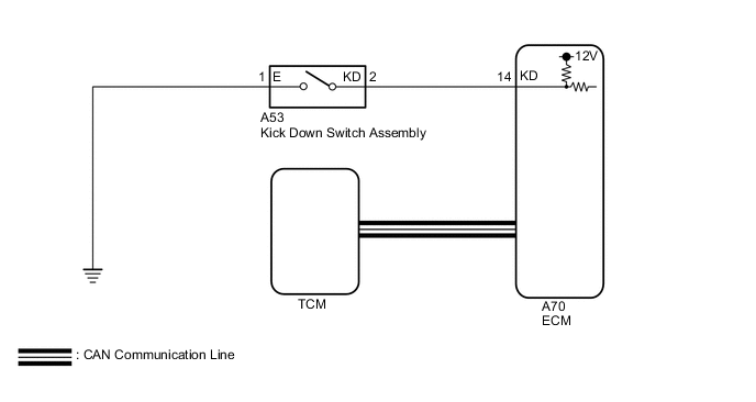
PROCEDURE
-
CHECK HARNESS AND CONNECTOR (KICK DOWN SWITCH ASSEMBLY - BODY GROUND)
-
Disconnect the A53 kick down switch assembly connector.
-
Measure the resistance according to the value(s) in the table below.
Standard Resistance Tester Connection Condition Specified Condition A53-1 (E) - Body ground Always Below 1 Ω Result Proceed to OK NG
NG 
REPAIR OR REPLACE HARNESS OR CONNECTOR (KICK DOWN SWITCH ASSEMBLY - BODY GROUND)
OK 
-
-
INSPECT KICK DOWN SWITCH ASSEMBLY
-
Remove the kick down switch assembly.
for LHD: Click here
for RHD: Click here
-
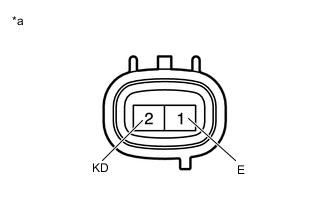
*a Component without harness connected
(Kick Down Switch Assembly)
Measure the resistance according to the value(s) in the table below.
Standard Resistance Tester Connection Condition Specified Condition 1 (E) - 2 (KD) Continuously press
(Kick down switch is on)
Below 1 Ω Released
(Kick down switch is off)
10 kΩ or higher Result Proceed to OK NG
NG
REPLACE KICK DOWN SWITCH ASSEMBLY for LHD: Click here
REPLACE KICK DOWN SWITCH ASSEMBLY for RHD: Click hereOK
-
-
CHECK HARNESS AND CONNECTOR (KICK DOWN SWITCH ASSEMBLY - ECM)
-
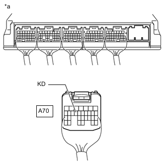
*a Rear view of wire harness connector
(to ECM)
Install the kick down switch assembly.
-
Disconnect the A70 ECM connector.
-
Measure resistance according to the value(s) in the table below.
Standard Resistance Tester Connection Condition Specified Condition A70-14 (KD) - Body ground Fully depressed
(Kick down switch is on)
Below 1 Ω Released
(Kick down switch is off)
10 kΩ or higher Result Proceed to OK NG
OK
PROCEED TO NEXT SUSPECTED AREA SHOWN IN PROBLEM SYMPTOMS TABLE Click here
NG
REPAIR OR REPLACE HARNESS OR CONNECTOR (KICK DOWN SWITCH ASSEMBLY - ECM)
-