AUTOMATIC TRANSMISSION SYSTEM(for 2GR-FSE), Diagnostic DTC:P0617
| DTC Code | DTC Name |
|---|---|
| P0617 | Starter Relay Circuit High |
DESCRIPTION
While the engine is being cranked, battery voltage is applied to terminal STA of the TCM.
If the TCM detects the starter control (STA) signal while the vehicle is being driven, it determines that there is a malfunction in the STA circuit. The TCM then illuminates the MIL and stores this DTC.
This monitor runs when the vehicle is driven at 20 km/h (12.4 mph) or more for more than 20 seconds.
| DTC No. | Detection Item | DTC Detection Condition | Trouble Area | MIL | Memory |
|---|---|---|---|---|---|
| P0617 | Starter Relay Circuit High | 1. Diagnosis Condition 2. Malfunction Status 3. Malfunction Time 4. Other
|
|
Comes on | DTC stored |
WIRING DIAGRAM
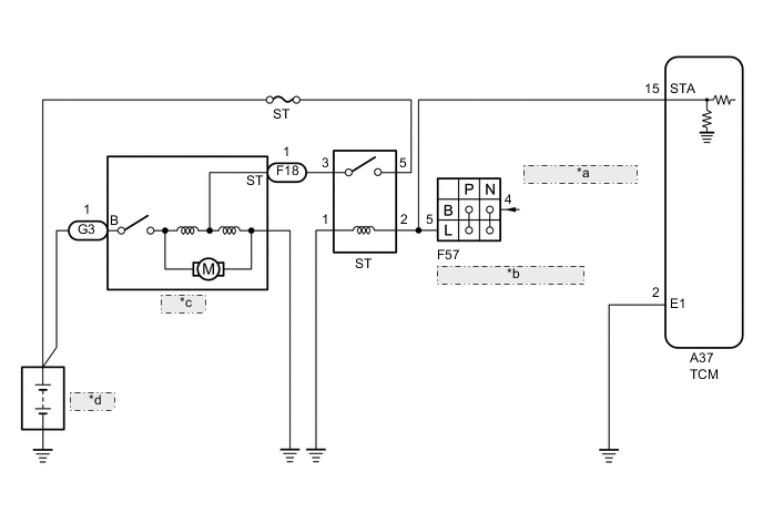
| *a | from Certification ECU (Smart Key ECU Assembly) |
| *b | Park/Neutral Position Switch Assembly |
| *c | Starter |
| *d | Battery |
CAUTION / NOTICE / HINT
Note
Perform registration and/or initialization when parts related to the automatic transmission are replaced.
Tech Tips
After the repair, clear the DTCs and perform the following procedure to check that DTCs are not output.
-
Drive the vehicle for 20 seconds or more under the following conditions:
-
Engine speed is 1000 rpm or more.
-
Vehicle speed is 20 km/h (13 mph) or more.
-
Check for DTCs again.
PROCEDURE
-
READ VALUE USING GTS (STARTER SIGNAL)
-
Connect the GTS to the DLC3.
-
Turn the engine switch on (IG).
-
Turn the GTS on.
-
Enter the following menus: Powertrain / ECT / Data List / Starter Signal.
Powertrain > ECT > Data ListTester Display Measurement Item Range Normal Condition Diagnostic Note Starter Signal Starter signal ON or OFF
-
ON: Engine is cranking
-
OFF: Engine switch on (IG)
-
Powertrain > ECT > Data ListTester Display Starter Signal -
-
Check the value displayed on the GTS when the vehicle is driven at 20 km/h (12.4 mph) or more.
CAUTION:
When performing the confirmation driving pattern, obey all speed limits and traffic laws.
Result Condition GTS Display Proceed to Driving at 20 km/h (12.4 mph) or more OFF A ON B
A 
SYMPTOMS SIMULATION AND DTC CHECK Click here
B 
-
-
INSPECT PARK/NEUTRAL POSITION SWITCH ASSEMBLY
-
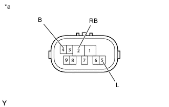
*a Component without harness connected
(Park/Neutral Position Switch Assembly)
Disconnect the F57 park/neutral position switch assembly connector.
-
Measure the resistance according to the value(s) in the table below.
Standard Resistance Tester Connection Condition Specified Condition 4 (B) - 5 (L) Shift lever in P Below 1 Ω Shift lever in N Below 1 Ω Shift lever not in P or N 10 kΩ or higher 2 (RB) - 5 (L) Shift lever in P 10 kΩ or higher Shift lever in R 10 kΩ or higher Shift lever in N 10 kΩ or higher Shift lever in D 10 kΩ or higher Result Proceed to OK NG
NG
REPLACE PARK/NEUTRAL POSITION SWITCH ASSEMBLY Click here
OK
-
-
CHECK HARNESS AND CONNECTOR (TCM - PARK/NEUTRAL POSITION SWITCH ASSEMBLY)
-
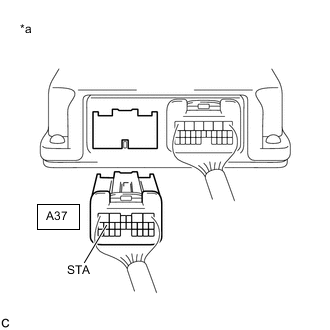
*a Rear view of wire harness connector
(to TCM)
Disconnect the A37 TCM connector.
-
Remove the ST relay from the No. 1 engine room relay block and No. 1 junction block assembly.
-
Turn the engine switch on (IG).
-
Measure the voltage according to the value(s) in the table below.
Standard Voltage Tester Connection Condition Specified Condition A37-15 (STA) - Body ground Engine switch on (IG) Below 2 V Result Proceed to OK NG
NG
REPAIR OR REPLACE HARNESS OR CONNECTOR (TCM - PARK/NEUTRAL POSITION SWITCH ASSEMBLY)
OK
-
-
CLEAR THE DTC AND RUNNING TEST
-
Connect the GTS to the DLC3.
-
Start the engine and turn the GTS on.
-
Enter the following menus: Powertrain / ECT / Trouble Codes.
Powertrain > ECT > Clear DTCs -
Clear the DTCs.
Tech Tips
Write down the currently output DTCs before clearing them.
-
Perform the monitor drive pattern.
-
Enter the following menus: Powertrain / ECT / Trouble Codes.
Powertrain > ECT > Trouble Codes -
Read the DTCs using the GTS.
Result Result Proceed to DTCs are not output A DTC P0617 is output B
A
END
B
-
-
REPLACE TCM
-
Replace the TCM.
Result Proceed to NEXT
NEXT
PERFORM A/T CODE REGISTRATION Click here
-