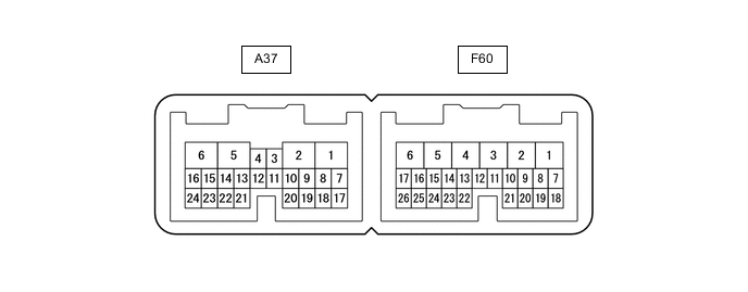
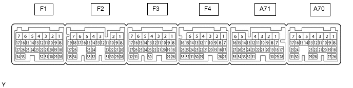
AUTOMATIC TRANSMISSION SYSTEM(for 2GR-FSE) TERMINALS OF ECU
-
TCM
Tech Tips
The standard voltage and resistance of each TCM terminal is shown in the table below.
In the table, first follow the information under "Condition". Look under "Terminal No. (Symbol)" for the terminals to be inspected. The standard voltage or resistance between the terminals is shown under "Specified Condition".
Use the illustration above as a reference for the TCM terminals.
Terminal No. (Symbol) Wiring Color Terminal Description Condition Specified Condition A37-1 (E01) - Body ground W-B - Body ground Ground Always Below 1 Ω A37-2 (E1) - Body ground W-B - Body ground Ground Always Below 1 Ω A37-3 (P) - A37-2 (E1) W - W-B Park position switch signal Engine switch on (IG) and shift lever in P 11 to 14 V A37-3 (P) - A37-2 (E1) W - W-B Park position switch signal Engine switch on (IG) and shift lever not in P Below 1 V A37-5 (+B) - A37-2 (E1) B-R - W-B Power source of TCM Engine switch on (IG) 11 to 14 V A37-6 (BATT) - A37-2 (E1) L - W-B Battery (for measuring battery voltage and for TCM memory) Always 11 to 14 V A37-10 (N) - A37-2 (E1) R - W-B N shift position switch signal Engine switch on (IG) and shift lever in N 11 to 14 V A37-10 (N) - A37-2 (E1) R - W-B N shift position switch signal Engine switch on (IG) and shift lever not in N Below 1 V A37-11 (R) - A37-2 (E1) G - W-B R shift position switch signal Engine switch on (IG) and shift lever in R 11 to 14 V A37-11 (R) - A37-2 (E1) G - W-B R shift position switch signal Engine switch on (IG) and shift lever not in R Below 1 V A37-13 (CAN-) - A37-2 (E1) W - W-B CAN communication line Engine switch on (IG) Pulse generation
(see waveform 12)
A37-15 (STA) - A37-2 (E1) R - W-B Starter signal Cranking (shift lever in P or N, engine switch start) 11 to 14 V A37-15 (STA) - A37-2 (E1) R - W-B Starter signal Engine switch on (IG) and shift lever in P or N Below 2 V A37-16 (IG2) - A37-2 (E1) B - W-B Engine switch Engine switch on (IG) 11 to 14 V A37-20 (D) - A37-2 (E1) Y - W-B D shift position switch signal Engine switch on (IG) and shift lever in D or M 11 to 14 V A37-20 (D) - A37-2 (E1) Y - W-B D shift position switch signal Engine switch on (IG) and shift lever not in D or M Below 1 V A37-21 (CAN+) - A37-2 (E1) B - W-B CAN communication line Engine switch on (IG) Pulse generation
(see waveform 11)
A37-23 (STP) - A37-2 (E1) R - W-B Stop light switch signal Brake pedal depressed 7.5 to 14 V A37-23 (STP) - A37-2 (E1) R - W-B Stop light switch signal Brake pedal released Below 1 V F60-12 (THO1) - F60-13 (E2) L - V ATF temperature sensor signal ATF temperature 115°C (239°F) or more Below 1.5 V F60-6 (SL1+) - F60-5 (SL1-) Y - GR Shift solenoid valve SL1 signal 1st, 2nd, 3rd, 4th or 5th gear Pulse generation
(see waveform 1)
F60-4 (SL2+) - F60-14 (SL2-) B - G Shift solenoid valve SL2 signal 5th, 6th, 7th or 8th gear Pulse generation
(see waveform 2)
F60-26 (SL3+) - F60-25 (SL3-) R- G Shift solenoid valve SL3 signal 3rd or 7th gear Pulse generation
(see waveform 3)
F60-17 (SL4+) - F60-16 (SL4-) L - Y Shift solenoid valve SL4 signal 4th or 6th gear Pulse generation
(see waveform 4)
F60-3 (SL5+) - F60-10 (SL5-) R - W Shift solenoid valve SL5 signal 2nd or 8th gear Pulse generation
(see waveform 5)
F60-1 (SLT+) - F60-7 (SLT-) G - BR Shift solenoid valve SLT signal Engine idling Pulse generation
(see waveform 6)
F60-2 (SLU+) - F60-8 (SLU-) R - L Shift solenoid valve SLU signal D position:
4th, 5th, 6th, 7th or 8th gear
(Flex lock-up ON and Lock-up ON )
M position:
2nd, 3rd, 4th, 5th, 6th, 7th or 8th gear
(Lock-up ON )
Pulse generation
(see waveform 7)
F60-24 (SL) - A37-2 (E1) B - W-B Shift solenoid valve SL signal D position:
4th, 5th, 6th, 7th or 8th gear
(Flex lock-up ON and Lock-up ON)
M position:
2nd, 3rd, 4th, 5th, 6th, 7th or 8th gear
(Lock-up ON)
11 to 14 V F60-15 (SR) - A37-2 (E1) GR - W-B Shift solenoid valve SR signal All gears 11 to 14 V F60-21 (NTB) - A37-2 (E1) R - W-B Power source for sensor
(specific voltage)
Engine switch on (IG) 11 to 14 V F60-20 (NTO) - A37-2 (E1) G - W-B Transmission Revolution Sensor (NT) signal Engine idling (shift lever in P or N) Pulse generation
(see waveform 8)
F60-19 (NC3B) - A37-2 (E1) R - W-B Power source for sensor
(specific voltage)
Engine switch on (IG) 11 to 14 V F60-18 (NC3O) - A37-2 (E1) B - W-B Transmission Revolution Sensor (NC3) signal 1st, 3rd, 4th, 5th, 6th or 7th gear Pulse generation
(see waveform 9)
F60-23 (SP2B) - A37-2 (E1) L - W-B Power source for sensor
(specific voltage)
Engine switch on (IG) 11 to 14 V F60-22 (SP2O) - A37-2 (E1) Y - W-B Transmission Revolution Sensor (SP2) signal Vehicle speed 20 km/h (12 mph) Pulse generation
(see waveform 10)
F60-9 (TPS1) - A37-2 (E1) L - W-B Oil pressure switch signal 6th to 8th gear 11 to 14 V F60-9 (TPS1) - A37-2 (E1) L - W-B Oil pressure switch signal 1st to 5th gear Below 1 V
-
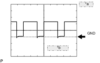
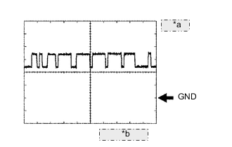
*a 5 V/DIV. *b 1 msec./DIV. Using an oscilloscope, check waveform 1.
Reference Item Content Terminal No. (Symbol) F60-6 (SL1+) - F60-5 (SL1-) Tool setting 5 V/DIV., 1 msec./DIV. Condition 1st, 2nd, 3rd, 4th or 5th gear -
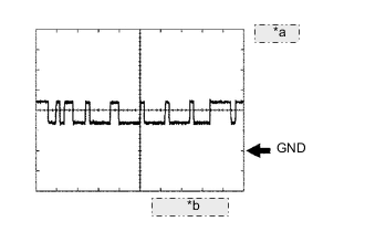
*a 5 V/DIV. *b 1 msec./DIV. Using an oscilloscope, check waveform 2.
Reference Item Content Terminal No. (Symbol) F60-4 (SL2+) - F60-14 (SL2-) Tool setting 5 V/DIV., 1 msec./DIV. Condition 5th, 6th, 7th or 8th gear -
*a 5 V/DIV. *b 1 msec./DIV. Using an oscilloscope, check waveform 3.
Reference Item Content Terminal No. (Symbol) F60-26 (SL3+) - F60-25 (SL3-) Tool setting 5 V/DIV., 1 msec./DIV. Condition 3rd or 7th gear -
*a 5 V/DIV. *b 1 msec./DIV. Using an oscilloscope, check waveform 4.
Reference Item Content Terminal No. (Symbol) F60-17 (SL4+) - F60-16 (SL4-) Tool setting 5 V/DIV., 1 msec./DIV. Condition 4th or 6th gear -
*a 5 V/DIV. *b 1 msec./DIV. Using an oscilloscope, check waveform 5.
Reference Item Content Terminal No. (Symbol) F60-3 (SL5+) - F60-10 (SL5-) Tool setting 5 V/DIV., 1 msec./DIV. Condition 2nd or 8th gear -
*a 5 V/DIV. *b 1 msec./DIV. Using an oscilloscope, check waveform 6.
Reference Item Content Terminal No. (Symbol) F60-1 (SLT+) - F60-7 (SLT-) Tool setting 5 V/DIV., 1 msec./DIV. Condition Engine idling -
*a 5 V/DIV *b 1 msec./DIV Using an oscilloscope, check waveform 7.
Reference Item Content Terminal No. (Symbol) F60-2 (SLU+) - F60-8 (SLU-) Tool setting 5 V/DIV., 1 msec./DIV. Condition D position:
4th, 5th, 6th, 7th or 8th gear (Flex lock-up ON and Lock-up ON)
M position:
2nd, 3rd, 4th, 5th, 6th, 7th or 8th gear
(Lock-up ON)
-
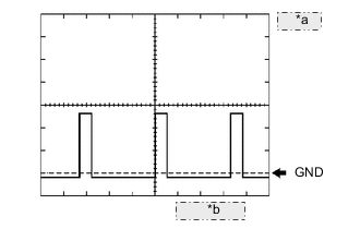
*a 1 V/DIV. *b 2 msec./DIV. Using an oscilloscope, check waveform 8.
Reference Item Content Terminal No. (Symbol) F60-20 (NTO) - A37-2 (E1) Tool setting 1 V/DIV., 2 msec./DIV. Condition Engine idling (shift lever in P or N) -
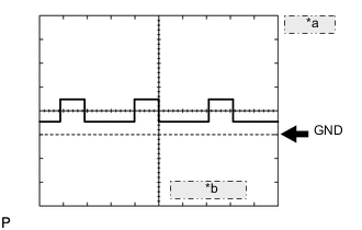
*a 1 V/DIV. *b 2 msec./DIV. Using an oscilloscope, check waveform 9.
Reference Item Content Terminal No. (Symbol) F60-18 (NC3O) - A37-2 (E1) Tool setting 1 V/DIV., 2 msec./DIV. Condition 1st, 3rd, 4th, 5th, 6th or 7th gear -
*a 1 V/DIV. *b 2 msec./DIV. Using an oscilloscope, check waveform 10.
Reference Item Content Terminal No. (Symbol) F60-22 (SP2O) - A37-2 (E1) Tool setting 1 V/DIV., 2 msec./DIV. Condition Vehicle speed 20 km/h (12 mph) -
*a 1 V/DIV *b 10 msec./DIV Using an oscilloscope, check waveform 11.
Reference Item Content Terminal No. (Symbol) A37-21 (CAN+) - A37-2 (E1) Tool setting 1 V/DIV., 10 msec./DIV. Condition Engine switch on (IG) -
*a 1 V/DIV *b 10 msec./DIV Using an oscilloscope, check waveform 12.
Reference Item Content Terminal No. (Symbol) A37-13 (CAN-) - A37-2 (E1) Tool setting 1 V/DIV., 10 msec./DIV. Condition Engine switch on (IG)
-
-
ECM
Tech Tips
The standard voltage of each ECM terminal is shown in the table below.
In the table, first follow the information under "Condition". Look under "Terminal No. (Symbol)" for the terminals to be inspected. The standard voltage between the terminals is shown under "Specified Condition".
Use the illustration above as a reference for the ECM terminals.
Terminal No. (Symbol) Wiring Color Terminal Description Condition Specified Condition A71-7 (SFTD) - F4-1 (E1) P - BR Down-shift position switch signal Engine switch on (IG) 11 to 14 V A71-7 (SFTD) - F4-1 (E1) P - BR Down-shift position switch signal
-
Engine switch on (IG) and shift lever held in "-"
-
Engine switch on (IG) and "-" paddle switch pulled
Below 1 V A71-8 (SFTU) - F4-1 (E1) V - BR Up-shift shift position switch signal Engine switch on (IG) 11 to 14 V A71-8 (SFTU) - F4-1 (E1) V - BR Up-shift shift position switch signal
-
Engine switch on (IG) and shift lever held in "+"
-
Engine switch on (IG) and "+" paddle switch pulled
Below 1 V A71-16 (S) - F4-1 (E1) GR - BR M shift position switch signal Engine switch on (IG) and shift lever in M 11 to 14 V A71-16 (S) - F4-1 (E1) GR - BR M shift position switch signal Engine switch on (IG) and shift lever not in M Below 1 V A70-14 (KD) - F4-1 (E1) B - BR Kick-down switch signal Engine switch on (IG) and accelerator pedal depressed Below 1 V A70-14 (KD) - F4-1 (E1) B - BR Kick-down switch signal Engine switch on (IG) and accelerator pedal released 11 to 14 V -