AUTOMATIC TRANSMISSION SYSTEM(for 8AR-FTS), Diagnostic DTC:P061512
| DTC Code | DTC Name |
|---|---|
| P061512 | Starter Relay Circuit Short to Battery |
DESCRIPTION
While the engine is being cranked, battery voltage is applied to terminal STA of the ECM.
If the ECM detects the starter control (STA) signal while the vehicle is being driven, it determines that there is a malfunction in the STA circuit. The ECM then illuminates the MIL and stores this DTC.
This monitor runs when the vehicle is driven at 20 km/h (12 mph) or more for 20 seconds or more.
| DTC No. | Detection Item | DTC Detection Condition | Trouble Area | MIL | Memory | Note |
|---|---|---|---|---|---|---|
| P061512 | Starter Relay Circuit Short to Battery | 1. Diagnosis Condition 2. Malfunction Status 3. Malfunction Time 4. Other
|
|
Comes on | DTC stored | SAE Code: P0617 |
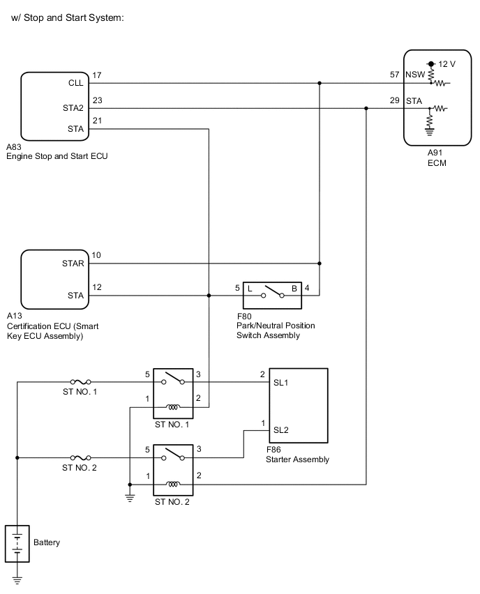
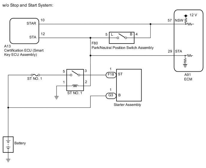
WIRING DIAGRAM
CAUTION / NOTICE / HINT
Note
-
Perform registration and/or initialization when parts related to the automatic transmission are replaced.
-
Inspect the fuses for circuits related to this system before performing the following procedure.
Tech Tips
After performing repair, clear the DTCs and perform the following procedure to check that DTCs are not output.
-
Drive the vehicle for 20 seconds or more under the following conditions:
-
Engine speed is 1000 rpm or more.
-
Vehicle speed is 20 km/h (12 mph) or more.
-
Check for DTCs again.
PROCEDURE
-
READ VALUE USING GTS (STARTER SW)
-
Connect the GTS to the DLC3.
-
Turn the engine switch on (IG)
-
Turn the GTS on.
-
Enter the following menus: Powertrain / Transmission / Data List / Starter SW.
Powertrain > Transmission > Data ListTester Display Measurement Item Range Normal Condition Diagnostic Note Starter SW Starter signal OFF or ON
-
ON: Starter operating
-
OFF: Starter not operating
-
Powertrain > Transmission > Data ListTester Display Starter SW -
-
According to the display on the GTS, read the Data List.
Standard Condition Starter SW Engine switch on (IG) OFF -
According to the display on the GTS, read the Data List while the vehicle is being driven with an engine speed of 1000 rpm or more at a vehicle speed of 20 km/h (12 mph) or more.
Standard Condition Starter SW Driving at 20 km/h (12 mph) or more (engine speed 1000 rpm or more) OFF Tech Tips
If the result of either of the above is not as specified, proceed to the next step with the engine switch on (IG), GTS connected and Data List item "Starter SW" selected.
Result Result Proceed to OK A NG (w/ Stop and Start System) B NG (w/o Stop and Start System) C Tech Tips
If the starter assembly operates continuously when the engine switch is turned on (IG), proceed to the next step without reading the Data List item "Starter SW".
A 
SYMPTOMS SIMULATION AND DTC CHECK Click here
C 
INSPECT ST NO. 1 RELAY (CHECK FOR SHORT CIRCUIT) Click here
B 
-
-
INSPECT ST NO. 2 RELAY (CHECK FOR SHORT CIRCUIT)
-
Enter the following menus: Powertrain / Transmission / Data List / Starter SW.
Powertrain > Transmission > Data ListTester Display Measurement Item Range Normal Condition Diagnostic Note Starter SW Starter signal OFF or ON
-
ON: Starter operating
-
OFF: Starter not operating
-
Powertrain > Transmission > Data ListTester Display Starter SW -
-
Remove the ST NO. 2 relay from the No. 1 engine room relay block and No. 1 junction block assembly.
-
According to the display on the GTS, read the Data List.
Result Result Proceed to The Data List item "Starter SW" does not change from ON. A The Data List item "Starter SW" changes from ON to OFF. B Tech Tips
-
When the result of the above inspection is "The Data List item "Starter SW" does not change from ON", the ST NO. 2 relay is normal.
-
DTCs may be stored during this inspection. Check for DTCs and clear them using the GTS.
-
B
REPLACE ST NO. 2 RELAY
A
-
-
CHECK TERMINAL VOLTAGE (POWER SOURCE OF ST NO. 2 RELAY)
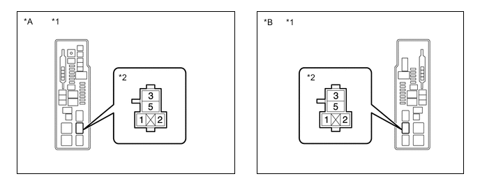
*A for LHD *B for RHD *1 No. 1 Engine Room Relay Block and No. 1 Junction Block Assembly *2 ST NO. 2 Relay Tech Tips
The purpose of this step is to check for ST NO. 2 relay terminal voltage under abnormal conditions.
-
Remove the ST NO. 2 relay from the No. 1 engine room relay block and No. 1 junction block assembly.
-
Turn the engine switch on (IG).
-
Measure the voltage between ST NO. 2 relay terminal 2 and body ground.
Tech Tips
-
Make a note of the measured voltage as it will be necessary for inspecting the change in voltage in the next step. As the next step should be conducted under the same conditions, keep the engine switch on (IG) and do not install the ST NO. 2 relay.
-
DTCs may be stored during this inspection. Check for DTCs and clear them using the GTS.
-
If any voltage was measured with the engine switch on (IG), one of the following malfunctions is suspected:
-
Short to +B in the circuit of a connected ECU.
-
Short to +B in the wire harness.
Result Proceed to NEXT -
NEXT
-
-
INSPECT ENGINE STOP AND START ECU (CHECK FOR SHORT CIRCUIT)
*A for LHD *B for RHD *1 No. 1 Engine Room Relay Block and No. 1 Junction Block Assembly *2 ST NO. 2 Relay
-
Disconnect the A83 engine stop and start ECU connector.
-
Measure the voltage between ST NO. 2 relay terminal 2 and body ground and compare it to the voltage measured in the previous step.
Result Result Proceed to The voltage between ST NO. 2 relay terminal 2 and body ground does not change when the connector is disconnected. A The voltage between ST NO. 2 relay terminal 2 and body ground changes when the connector is disconnected. B Tech Tips
-
If the voltage is the same before and after disconnecting the connector, the engine stop and start ECU is normal.
-
DTCs may be stored during this inspection. Check for DTCs and clear them using the GTS.
-
B
REPLACE ENGINE STOP AND START ECU Click here
A
-
-
INSPECT ECM (CHECK FOR SHORT CIRCUIT)
*A for LHD *B for RHD *1 No. 1 Engine Room Relay Block and No. 1 Junction Block Assembly *2 ST NO. 2 Relay
-
Disconnect the A91 ECM connector.
-
Measure the voltage between ST NO. 2 relay terminal 2 and body ground and compare it to the voltage measured in the previous step.
Result Result Proceed to The voltage between ST NO. 2 relay terminal 2 and body ground does not change when the connector is disconnected. A The voltage between ST NO. 2 relay terminal 2 and body ground changes when the connector is disconnected. B Tech Tips
-
If the voltage is the same before and after disconnecting the connector, the ECM is normal.
-
DTCs may be stored during this inspection. Check for DTCs and clear them using the GTS.
-
A
REPAIR OR REPLACE HARNESS OR CONNECTOR (STA SIGNAL CIRCUIT)
B
-
-
REPLACE ECM
-
Replace the ECM.
Result Proceed to NEXT
NEXT
PERFORM A/T CODE REGISTRATION Click here
-
-
INSPECT ST NO. 1 RELAY (CHECK FOR SHORT CIRCUIT)
-
Enter the following menus: Powertrain / Transmission / Data List / Starter SW.
Powertrain > Transmission > Data ListTester Display Measurement Item Range Normal Condition Diagnostic Note Starter SW Starter signal OFF or ON
-
ON: Starter operating
-
OFF: Starter not operating
-
Powertrain > Transmission > Data ListTester Display Starter SW -
-
Remove the ST NO. 1 relay from the No. 1 engine room relay block and No. 1 junction block assembly.
-
According to the display on the GTS, read the Data List.
Result Result Proceed to The Data List item "Starter SW" does not change from ON. A The Data List item "Starter SW" changes from ON to OFF. B Tech Tips
-
When the result of the above inspection is "The Data List item "Starter SW" does not change from ON", the ST NO. 1 relay is normal.
-
DTCs may be stored during this inspection. Check for DTCs and clear them using the GTS.
-
B
REPLACE ST NO. 1 RELAY
A
-
-
CHECK TERMINAL VOLTAGE (POWER SOURCE OF ST NO. 1 RELAY)
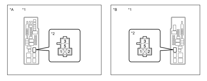
*A for LHD *B for RHD *1 No. 1 Engine Room Relay Block and No. 1 Junction Block Assembly *2 ST NO. 1 Relay Tech Tips
The purpose of this step is to check for ST NO. 1 relay terminal voltage under abnormal conditions.
-
Remove the ST NO. 1 relay from the No. 1 engine room relay block and No. 1 junction block assembly.
-
Turn the engine switch on (IG).
-
Measure the voltage between ST NO. 1 relay terminal 2 and body ground.
Tech Tips
-
Make a note of the measured voltage as it will be necessary for inspecting the change in voltage in the next step. As the next step should be conducted under the same conditions, keep the engine switch on (IG) and do not install the ST NO. 1 relay.
-
DTCs may be stored during this inspection. Check for DTCs and clear them using the GTS.
-
If any voltage was measured with the engine switch on (IG), one of the following malfunctions is suspected:
-
Short to +B in the circuit of a connected ECU or the park/neutral position switch assembly.
-
Short to +B in the wire harness.
Result Proceed to NEXT -
NEXT
-
-
INSPECT PARK/NEUTRAL POSITION SWITCH ASSEMBLY (CHECK FOR SHORT CIRCUIT)
*A for LHD *B for RHD *1 No. 1 Engine Room Relay Block and No. 1 Junction Block Assembly *2 ST NO. 1 Relay
-
Disconnect the F80 park/neutral position switch assembly connector.
-
Measure the voltage between ST NO. 1 relay terminal 2 and body ground and compare it to the voltage measured in the previous step.
Result Result Proceed to The voltage between ST NO. 1 relay terminal 2 and body ground does not change when the connector is disconnected. A The voltage between ST NO. 1 relay terminal 2 and body ground changes when the connector is disconnected. B Tech Tips
-
If the voltage is the same before and after disconnecting the connector, the park/neutral position switch assembly is normal.
-
DTCs may be stored during this inspection. Check for DTCs and clear them using the GTS.
-
B
REPLACE PARK/NEUTRAL POSITION SWITCH ASSEMBLY Click here
A
-
-
INSPECT ECM (CHECK FOR SHORT CIRCUIT)
*A for LHD *B for RHD *1 No. 1 Engine Room Relay Block and No. 1 Junction Block Assembly *2 ST NO. 1 Relay
-
Disconnect the A91 ECM connector.
-
Measure the voltage between ST NO. 1 relay terminal 2 and body ground and compare it to the voltage measured in the previous step.
Result Result Proceed to The voltage between ST NO. 1 relay terminal 2 and body ground does not change when the connector is disconnected. A The voltage between ST NO. 1 relay terminal 2 and body ground changes when the connector is disconnected. B Tech Tips
-
If the voltage is the same before and after disconnecting the connector, the ECM is normal.
-
DTCs may be stored during this inspection. Check for DTCs and clear them using the GTS.
-
B
REPLACE ECM Click here
A
-
-
CHECK HARNESS AND CONNECTOR (ECM - PARK/NEUTRAL POSITION SWITCH ASSEMBLY - SMART KEY ECU ASSEMBLY - ST NO. 1 RELAY)
-
Disconnect the A91 ECM connector.
-
Disconnect the F80 park/neutral position switch assembly connector.
-
Disconnect the A13 certification ECU (smart key ECU assembly) connector.
-
Remove the ST NO. 1 relay from the No. 1 engine room relay block and No. 1 junction block assembly.
-
Measure the resistance according to the value(s) in the table below.
Standard Resistance Tester Connection Condition Specified Condition A91-29 (STA), F80-5 (L), A13-12 (STA) or 2 (ST NO. 1 relay) - Other terminals Always 10 kΩ or higher Result Proceed to OK NG
OK
CHECK ENTRY AND START SYSTEM (CHECK FOR STA TERMINAL VOLTAGE OF SMART KEY ECU ASSEMBLY) Click here
NG
REPAIR OR REPLACE HARNESS OR CONNECTOR
-
-
REPLACE ECM
-
Replace the ECM.
Result Proceed to NEXT
NEXT
PERFORM A/T CODE REGISTRATION Click here
-