STOP AND START SYSTEM, Diagnostic DTC:P060A
| DTC Code | DTC Name |
|---|---|
| P060A | Internal Control Module Monitoring Processor Performance |
DESCRIPTION
The engine stop and start ECU can detect open circuits when signals such as the boost, standby request or overheating signal cannot be sent to the backup boost converter control IC from the stop and start control IC in the engine stop and start ECU.
If a CPU duty malfunction is detected, the engine stop and start ECU stores DTC P060A and blinks the stop and start cancel indicator light.
| DTC No. | Detection Item | DTC Detection Condition | Trouble Area | Warning Indicate | Memory |
|---|---|---|---|---|---|
| P060A | Internal Control Module Monitoring Processor Performance | The following condition continues for 1 second or more (2 trip detection logic):
|
|
Blinks | DTC stored |
CONFIRMATION DRIVING PATTERN
Tech Tips
DTCs for the stop and start system are not cleared even if the malfunction has been repaired. After repairing the malfunction, be sure to clear the DTCs.
-
Tech Tips
-
If the cable is disconnected from the negative (-) battery terminal, stop and start control is prohibited until refresh charge is completed. In this case, drive the vehicle approximately 5 to 60 minutes until refresh charge is completed and stop and start control operation is permitted.
-
Allow the engine to idle for 3 minutes after it is warmed up and check that the engine idle speed is within 50 rpm of the target idle speed.
CONFIRMATION AFTER TROUBLESHOOTING
-
Connect the GTS to the DLC3.
-
Turn the engine switch on (IG) and turn the GTS on.
-
Clear the DTCs.
Powertrain > Stop and Start > Clear DTCs -
Start the engine and warm it up.
-
Drive the vehicle at 7 km/h (4.3 mph) or more.
CAUTION:
When performing Confirmation Driving Pattern, obey all speed limits and traffic laws.
-
Depress the brake pedal and stop the vehicle.
-
Keep the engine stopped by stop and start control for 1 second or more. (Keep the shift lever in D.)
-
Release the brake pedal with the shift lever in D to start the engine.
-
Check that DTCs are not output.
Powertrain > Stop and Start > Trouble Codes
-
-
STOP AND START SYSTEM OPERATION CHECK
Tech Tips
If the cable is disconnected from the negative (-) battery terminal, stop and start control is prohibited until refresh charge is completed. In this case, drive the vehicle approximately 5 to 60 minutes until refresh charge is completed and stop and start control operation is permitted.
-
Start the engine and warm it up.
-
Turn the air conditioning system off.
-
Drive the vehicle at 7 km/h (4.3 mph) or more.
CAUTION:
When performing Confirmation Driving Pattern, obey all speed limits and traffic laws.
-
Depress the brake pedal and stop the vehicle.
-
Allow the engine to stop by stop and start control. (Keep the shift lever in D.)
-
Release the brake pedal with the shift lever in D to start the engine.
-
WIRING DIAGRAM
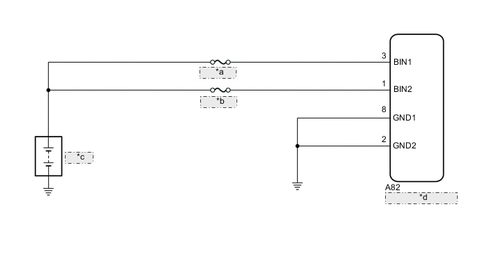
| *a | BBC NO. 1 |
| *b | BBC NO. 2 |
| *c | Battery |
| *d | Engine Stop and Start ECU |
CAUTION / NOTICE / HINT
Note
-
Before replacing the engine stop and start ECU, read the number of starter operations and total number of engine starts and write it into a new engine stop and start ECU.
-
After replacing the engine stop and start ECU or air conditioning amplifier assembly, reset and perform learning of the air conditioning information in the engine stop and start ECU.
-
After replacing the engine stop and start ECU or yaw rate sensor, clear and calibrate the deceleration sensor zero point in the engine stop and start ECU.
-
When the engine stop and start ECU is replaced, check the oil pump assembly with solenoid.
-
Inspect the fuses for circuits related to this system before performing the following procedure.
Tech Tips
Using the GTS, read the freeze frame data before troubleshooting. System condition information is recorded as freeze frame data the moment a DTC is stored. This information can be useful when troubleshooting.
PROCEDURE
-
CHECK HARNESS AND CONNECTOR (ENGINE STOP AND START ECU - BATTERY)
-
Disconnect the engine stop and start ECU connector.
-
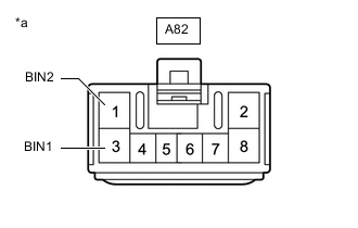
*a Front view of wire harness connector
(to Engine Stop and Start ECU)
Measure the voltage according to the value(s) in the table below.
Standard Voltage Tester Connection Condition Specified Condition A82-1 (BIN2) - Body ground Always 9.5 to 14 V A82-3 (BIN1) - Body ground Always 9.5 to 14 V Result Proceed to OK NG
NG 
REPAIR OR REPLACE HARNESS OR CONNECTOR
OK 
-
-
CHECK HARNESS AND CONNECTOR (ENGINE STOP AND START ECU - BODY GROUND)
-
Disconnect the A82 engine stop and start ECU connector.
-
Measure the resistance according to the value(s) in the table below.
Standard Resistance Tester Connection Condition Specified Condition A82-2 (GND2) - Body ground Always Below 1 Ω A82-8 (GND1) - Body ground Always Below 1 Ω Result Proceed to OK NG
OK
REPLACE ENGINE STOP AND START ECU Click here
NG
REPAIR OR REPLACE HARNESS OR CONNECTOR
-