MILLIMETER WAVE RADAR SENSOR ADJUSTMENT

PROCEDURE
-
ADJUST MILLIMETER WAVE RADAR SENSOR ASSEMBLY
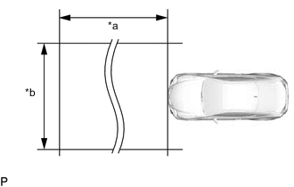
*a Approx. 10 m (32.8 ft.) *b Approx. 14 m (45.9 ft.) Note
-
Perform measurements on a level surface.
-
Make sure that no large metal objects are within a 10 m (32.8 ft.) x 14 m (45.9 ft.) area in front of the vehicle. If possible, the surrounding area should also be free of large metal objects.
-
Before adjusting the radar beam axis, prepare the vehicle as follows.
-
Check the tire pressure and adjust it if necessary.
-
Remove all excess weight from the vehicle (luggage, heavy objects, etc.).
-
Remove the engine room side cover Click here.
-
Remove the cool air intake duct seal Click here.
-
-
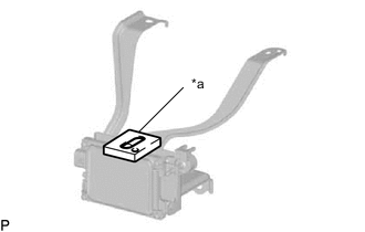
*a Level Check and adjust the vertical direction of the radar sensor.
-
Ensure that the radar sensor level rack is free from dust, oil and foreign matter.
-
Set a level on the radar sensor level rack.
-
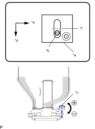
*a Level *b Air Bubble *c Bolt *d Vehicle Front *e Vehicle Left *f 0° Check that the air bubble of the level is within the red frame.
OK Air bubble of the level is within red frame. If the air bubble is not within the red frame, use a screwdriver to adjust the bolt until the air bubble is within the red frame.
Tech Tips
-
The adjustable range within the level's red frame is +/- 0.2°.
-
The target angle is +0.2° (upward angle of 0.2°).
Result Adjustment Direction Adjustment Procedure Adjustment Angle Upward Turn screwdriver to positive (+) side When screwdriver is turned once, angle changes approx. 0.14° Downward Turn screwdriver to negative (-) side
-
-
-
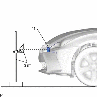
*1 Millimeter Wave Radar Sensor Adjust the reflector height.
-
Adjust the reflector so that the center of SST (reflector) is the same height as the millimeter wave radar sensor.
- SST
- 09870-60000 ( 09870-60010 )
- 09870-60040
Tech Tips
Prepare a 10 m (32.8 ft.) string, a string with a sharp-pointed weight (plumb bob) and a 5 m (16.4 ft.) tape measure.
-
-
Place the reflector.
-
Hang the string (with weight) from the center of the vehicle rear emblem. Mark the vehicle rear center point on the ground.
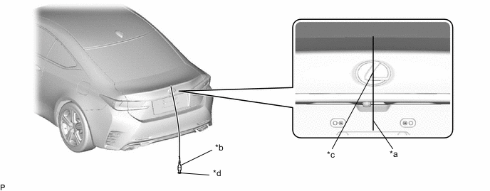
*a String *b Weight *c Center point *d Mark -
Repeat for the front of the vehicle.
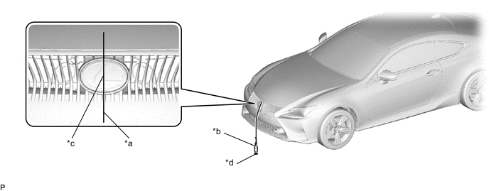
*a String *b Weight *c Center point *d Mark -
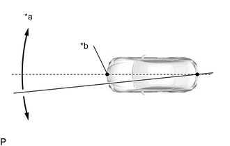
*a Adjust center by moving string to right and left *b Extend string through front center point Using tape and a string, create a line that connects the vehicle rear center point to the vehicle front center point and extends at least 5000 mm (16.4 ft.) beyond the vehicle front center point.
-
Mark a point (reflector placement point) on the line at a position 5000 mm (16.4 ft.) from the vehicle front center point.
-
Place SST (reflector) at the marked position.
Note
Perform the operation as precisely as possible.
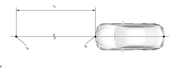
*a Reflector Placement Point *b Millimeter Wave Radar Sensor Position *c 5000 mm (16.4 ft.) - -
-
-
Check the radar beam axis.
-
When using the GTS:
-
Connect the GTS to the DLC3.
-
Turn the engine switch on (IG).
-
Turn the GTS on and turn the cruise control system on using the cruise control main switch.
-
Enter the following menus: Powertrain / Radar Cruise / Utility.
-
Follow the GTS display and continue with the adjustment.
CAUTION:
Do not come within 20 cm (7.87 in.) of the radar sensor.
Note
-
Turn the cruise control main switch on before pressing "Next".
-
Make sure there is at least 20 cm (7.87 in.) between the millimeter wave radar sensor and any nearby individuals.
-
If "Error beam axis" is displayed on the screen, press the "Yes" button, and repeat again.
-
Check that there are no metal objects in the specified area in front of the vehicle (refer to the NOTICE at the beginning of this adjustment procedure).
-
Powertrain > Radar Cruise > UtilityTester Display Beam Axis Adjustment -
-
Press the "Exit" button to finish beam axis adjustment.
-
Disconnect the GTS from the DLC3.
-
-
After adjusting the radar beam axis, return the vehicle to its original condition.
-
Install the cool air intake duct seal Click here.
-
Install the engine room side cover Click here.
-
If any heavy items were removed from the vehicle, return them (luggage, heavy objects, etc.).
-
-