DYNAMIC RADAR CRUISE CONTROL SYSTEM, Diagnostic DTC:U0235, U1104
| DTC Code | DTC Name |
|---|---|
| U0235 | Lost Communication with Cruise Control Front Distance Range Sensor |
| U1104 | Lost Communication with Driving Support ECU |
DESCRIPTION
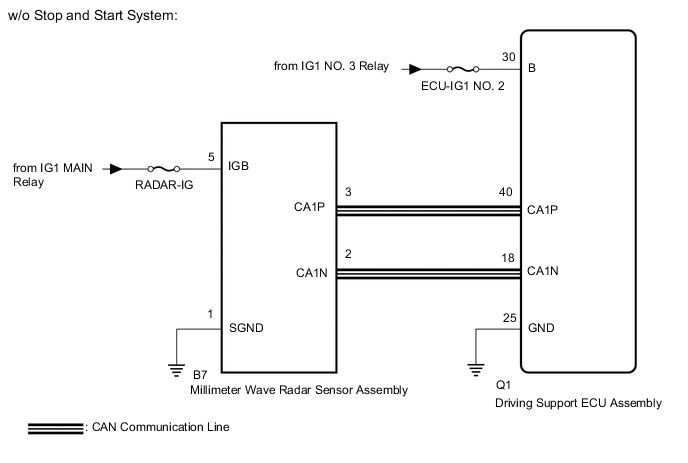
The driving support ECU assembly sends vehicle speed and vehicle condition information to the millimeter wave radar sensor assembly. The millimeter wave radar sensor assembly then sends information on the presence, distance, and relative speed of objects ahead to the driving support ECU assembly. The driving support ECU assembly sends this information to the ECM and performs dynamic radar cruise control system operation.
| DTC No. | Detection Item | DTC Detection Condition | Trouble Area |
|---|---|---|---|
| U0235 | Lost Communication with Cruise Control Front Distance Range Sensor | When the cruise control switch is on and the vehicle is being driven at a speed of 36 km/h (22 mph) or more, a communication error between the millimeter wave radar sensor assembly and the driving support ECU assembly is detected for approximately 1 second. |
|
| U1104 | Lost Communication with Driving Support ECU | When the cruise control switch is on and the vehicle is being driven at a speed of 36 km/h (22 mph) or more, a communication error between the driving support ECU assembly and the millimeter wave radar sensor assembly is detected for approximately 1 second. |
|
WIRING DIAGRAM
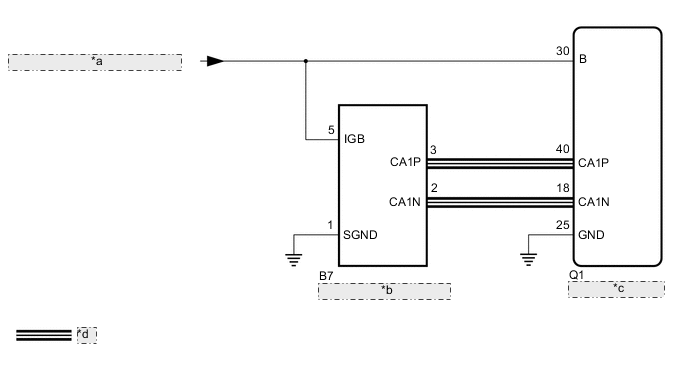
| *a | from Engine Stop and Start ECU |
| *b | Millimeter Wave Radar Sensor Assembly |
| *c | Driving Support ECU Assembly |
| *d | CAN Communication Line |
CAUTION / NOTICE / HINT
Note
Inspect the fuses for circuits related to this system before performing the following procedure.
PROCEDURE
-
CHECK HARNESS AND CONNECTOR (DRIVING SUPPORT ECU ASSEMBLY - MILLIMETER WAVE RADAR SENSOR ASSEMBLY)
-
Disconnect the Q1 driving support ECU assembly connector.
-
Disconnect the B7 millimeter wave radar sensor assembly connector.
-
Measure the resistance according to the value(s) in the table below.
Standard Resistance Tester Connection Condition Specified Condition Q1-40 (CA1P) - B7-3 (CA1P) Always Below 1 Ω Q1-18 (CA1N) - B7-2 (CA1N) Always Below 1 Ω Q1-40 (CA1P) or B7-3 (CA1P) - Body ground Always 10 kΩ or higher Q1-18 (CA1N) or B7-2 (CA1N) - Body ground Always 10 kΩ or higher Result Proceed to OK NG
NG 
REPAIR OR REPLACE HARNESS OR CONNECTOR
OK 
-
-
CHECK TERMINAL VOLTAGE (POWER SOURCE OF DRIVING SUPPORT ECU ASSEMBLY)
-
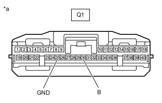
*a Front view of wire harness connector
(to Driving Support ECU Assembly)
Disconnect the Q1 driving support ECU assembly connector.
-
Measure the voltage and resistance according to the value(s) in the table below.
Standard Voltage Tester Connection Condition Specified Condition Q1-30 (B) - Body ground Engine switch on (IG) 11 to 14 V Q1-30 (B) - Body ground Engine switch off Below 1 V Standard Resistance Tester Connection Condition Specified Condition Q1-25 (GND) - Body ground Always Below 1 Ω Result Proceed to OK NG
NG
REPAIR OR REPLACE HARNESS OR CONNECTOR (DRIVING SUPPORT ECU ASSEMBLY - BATTERY AND BODY GROUND)
OK
-
-
CHECK TERMINAL VOLTAGE (POWER SOURCE OF MILLIMETER WAVE RADAR SENSOR ASSEMBLY)
-
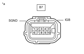
*a Front view of wire harness connector
(to Millimeter Wave radar sensor assembly)
Disconnect the B7 millimeter wave radar sensor assembly connector.
-
Measure the voltage and resistance according to the value(s) in the table below.
Standard Voltage Tester Connection Condition Specified Condition B7-5 (IGB) - Body ground Engine switch on (IG) 11 to 14 V B7-5 (IGB) - Body ground Engine switch off Below 1 V Standard Resistance Tester Connection Condition Specified Condition B7-1 (SGND) - Body ground Always Below 1 Ω Result Proceed to OK NG
NG
REPAIR OR REPLACE HARNESS OR CONNECTOR (MILLIMETER WAVE RADAR SENSOR ASSEMBLY - BATTERY AND BODY GROUND)
OK
-
-
REPLACE MILLIMETER WAVE RADAR SENSOR ASSEMBLY
-
Replace the millimeter wave radar sensor assembly with a new one.
-
Perform millimeter wave radar sensor assembly adjustment.
Result Proceed to NEXT
NEXT
-
-
CHECK FOR DTCs (RADAR CRUISE)
-
Clear the DTCs.
Powertrain > Radar Cruise > Clear DTCs -
Make sure that the DTC detection conditions are met.
Tech Tips
If the detection conditions are not met, the system cannot detect the malfunction.
-
Check for DTCs.
Powertrain > Radar Cruise > Trouble CodesNote
When replacing the driving support ECU assembly, always replace it with a new one. If a driving support ECU assembly which was installed to another vehicle is used, the information stored in the driving support ECU assembly will not match the information from the vehicle. As a result, a DTC may be stored.
Result Result Proceed to DTC U0235 and U1104 are not output A DTC U0235 or U1104 is output B
A
END (MILLIMETER WAVE RADAR SENSOR ASSEMBLY WAS DEFECTIVE)
B
REPLACE DRIVING SUPPORT ECU ASSEMBLY Click here
-