OIL PUMP INSPECTION

PROCEDURE
-
INSPECT OIL PUMP RELIEF VALVE
-
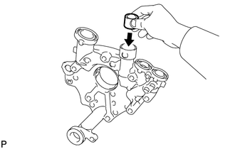
Coat the oil pump relief valve with engine oil and check that it falls smoothly into the valve hole by its own weight.
Tech Tips
If the oil pump relief valve does not fall smoothly, replace the timing chain cover assembly.
-
-
INSPECT OIL PUMP ROTOR SET
-
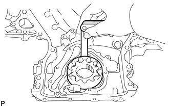
Apply engine oil to the drive rotor and driven rotor.
-
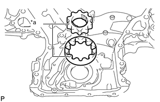
*a Mark Install the drive rotor and driven rotor to the timing chain cover assembly with the rotor marks facing up. Check that the rotors rotate smoothly.
Tech Tips
If the rotors do not rotate smoothly, replace the timing chain cover assembly.
-
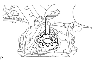
Check the tip clearance.
-
Using a feeler gauge, measure the clearance between the drive rotor and driven rotor tips as shown in the illustration.
Standard Tip Clearance 0.06 to 0.16 mm (0.00236 to 0.00630 in.) Maximum Tip Clearance 0.16 mm (0.00630 in.) Tech Tips
If the tip clearance is more than the maximum, replace the timing chain cover assembly.
-
-
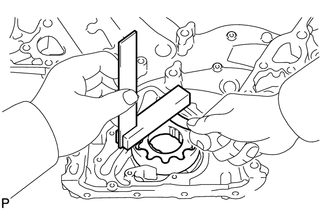
Check the side clearance.
-
Using a feeler gauge and steel square, measure the clearance between the drive rotor and driven rotor and precision straightedge as shown in the illustration.
Standard Side Clearance 0.030 to 0.075 mm (0.00118 to 0.00295 in.) Maximum Side Clearance 0.075 mm (0.00295 in.) Tech Tips
If the side clearance is more than the maximum, replace the timing chain cover assembly.
-
-
Check the rotor body clearance.
-
Using a feeler gauge, measure the clearance between the timing chain cover assembly and driven rotor as shown in the illustration.
Standard Body Clearance 0.250 to 0.325 mm (0.00984 to 0.0128 in.) Maximum Body Clearance 0.325 mm (0.0128 in.) Tech Tips
If the body clearance is more than the maximum, replace the timing chain cover assembly.
-
-