EXHAUST MANIFOLD INSTALLATION
PROCEDURE
-
INSTALL EXHAUST MANIFOLD SUB-ASSEMBLY LH (TWC: Front Catalyst)
-
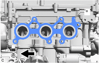
*a Protrusion 
Front Install a new exhaust manifold to head gasket LH to the cylinder head sub-assembly.
Tech Tips
Orient the protrusion of the exhaust manifold to head gasket LH as shown in the illustration.
-
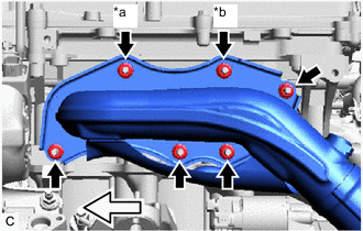
*a Nut (A) *b Nut (B) 
Front Temporarily install the exhaust manifold sub-assembly LH (TWC: Front Catalyst) with 6 new nuts.
-
Using a 12 mm deep socket wrench, tighten the 6 nuts.
- Torque:
- 21 N*m { 214 kgf*cm, 15 ft.*lbf }
Note
-
Be sure to tighten either the nut (A) or (B) shown in the illustration first.
-
Do not damage the stud bolts when installing the exhaust manifold sub-assembly LH (TWC: Front Catalyst).
-
-
INSTALL EXHAUST MANIFOLD SUB-ASSEMBLY RH (TWC: Front Catalyst)
-
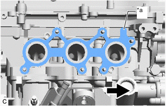
*a Protrusion Front Install a new exhaust manifold to head gasket to the cylinder head sub-assembly.
Tech Tips
Orient the protrusion of the exhaust manifold to head gasket as shown in the illustration.
-
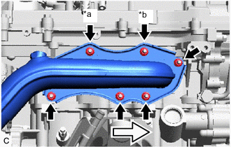
*a Nut (A) *b Nut (B) Front Temporarily install the exhaust manifold sub-assembly RH (TWC: Front Catalyst) with 6 new nuts.
-
Using a 12 mm deep socket wrench, tighten the 6 nuts.
- Torque:
- 21 N*m { 214 kgf*cm, 15 ft.*lbf }
Note
-
Be sure to tighten either the nut (A) or (B) shown in the illustration first.
-
Do not damage the stud bolts when installing the exhaust manifold sub-assembly RH (TWC: Front Catalyst).
-
-
INSTALL NO. 2 ENGINE OIL LEVEL DIPSTICK GUIDE
-
Install a new O-ring to the No. 2 engine oil level dipstick guide.
Tech Tips
Apply a light coat of engine oil to the O-ring.
-
Install the No. 2 engine oil level dipstick guide to the camshaft housing sub-assembly RH with the bolt.
- Torque:
- 21 N*m { 214 kgf*cm, 15 ft.*lbf }
-
Install the engine oil level dipstick.
-
-
INSTALL NO. 1 EXHAUST PIPE SUPPORT BRACKET SUB-ASSEMBLY
-
Install the No. 1 exhaust pipe support bracket sub-assembly to the automatic transmission with transfer assembly with the 2 bolts.
- Torque:
- 43 N*m { 438 kgf*cm, 32 ft.*lbf }
-
-
INSTALL FRONT EXHAUST PIPE ASSEMBLY (TWC: Rear Catalyst)
-
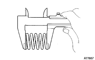
Using a vernier caliper, measure the free length of the compression springs.
Standard length 40 mm (1.57 in.) Minimum free length 38.5 mm (1.52 in.) If the free length is less than the minimum, replace the compression spring.
-
Temporarily install 2 new exhaust pipe gaskets to the front exhaust pipe assembly (TWC: Rear Catalyst) for tail exhaust pipe assembly and tail exhaust pipe LH side.
-
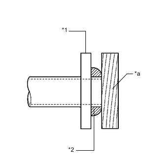
*1 Front Exhaust Pipe Assembly (TWC: Rear Catalyst) *2 Exhaust Pipe Gasket *a Wooden Block Using a plastic hammer and wooden block, tap in each exhaust pipe gasket until its surface is flush with the front exhaust pipe assembly (TWC: Rear Catalyst).
Note
-
Be sure to install the gaskets in the correct direction.
-
Do not reuse the gaskets.
-
Do not damage the gaskets.
-
Do not push in the gaskets by using the exhaust pipes when connecting them.
-
-
Install 2 new exhaust pipe gaskets to the front exhaust pipe assembly (TWC: Rear Catalyst) for exhaust manifold sub-assembly LH (TWC: Front Catalyst) and exhaust manifold sub-assembly RH (TWC: Front Catalyst) side.
-
Connect the front exhaust pipe assembly (TWC: Rear Catalyst) with 4 new nuts and 4 new bolts.
- Torque:
- 39 N*m { 398 kgf*cm, 29 ft.*lbf }
-
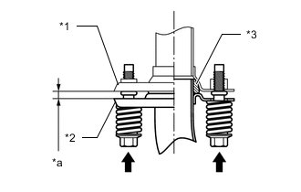
*1 Tail Exhaust Pipe Assembly or Tail Exhaust Pipe LH *2 Front Exhaust Pipe Assembly (TWC: Rear Catalyst) *3 Exhaust Pipe Gasket *a Space between Flanges: 6.5 mm (0.256 in.) Install the front exhaust pipe assembly (TWC: Rear Catalyst) to the tail exhaust pipe assembly and tail exhaust pipe LH with the 4 bolts and 4 compression springs.
- Torque:
- 43 N*m { 438 kgf*cm, 32 ft.*lbf }
Tech Tips
After installation, check that the space between the flanges of the front exhaust pipe assembly (TWC: Rear Catalyst) and tail exhaust pipe assembly and tail exhaust pipe LH is consistent front-to-rear and left-to-right.
-
for Bank 1:
-
Connect the heated oxygen sensor grommet to the vehicle body.
-
-
for Bank 2:
-
Connect the heated oxygen sensor grommet to the vehicle body.
-
-
-
CONNECT HEATED OXYGEN SENSOR CONNECTOR
-
INSTALL FRONT CENTER FLOOR BRACE
-
INSTALL FRONT CENTER FLOOR COVER LH (for Full Cover Type)
-
INSTALL FRONT CENTER FLOOR COVER RH (for Full Cover Type)
-
INSTALL NO. 2 ENGINE UNDER COVER (w/ No. 2 Engine Under Cover)
-
INSTALL FRONT SUSPENSION MEMBER BRACE
-
INSTALL AIR FUEL RATIO SENSOR
-
CONNECT NO. 1 ENGINE ROOM RELAY BLOCK AND NO. 1 JUNCTION BLOCK ASSEMBLY (for RHD)
-
Connect the No. 1 engine room relay block and No. 1 junction block assembly to the vehicle body with the 2 bolts and nut.
- Torque:
- 8.0 N*m { 82 kgf*cm, 71 in.*lbf }
-
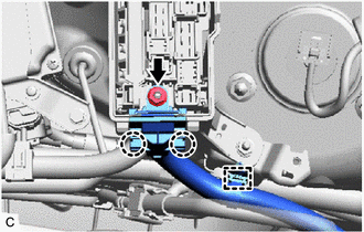
Connect the No. 4 engine wire holder and engage the 2 claws to the No. 1 engine room relay block and No. 1 junction block assembly.
-
Install the nut.
- Torque:
- 10.5 N*m { 107 kgf*cm, 8 ft.*lbf }
-
Engage the wire harness clamp to the vehicle body.
-
Install the No. 1 engine room relay block and No. 1 junction block assembly cover.
-
-
CONNECT CABLE TO NEGATIVE BATTERY TERMINAL (for RHD)
Note
When disconnecting the cable, some systems need to be initialized after the cable is reconnected.
-
INSPECT FOR EXHAUST GAS LEAK