TURBOCHARGER INSTALLATION
PROCEDURE
-
INSTALL INLET TURBO OIL PIPE SUB-ASSEMBLY
-
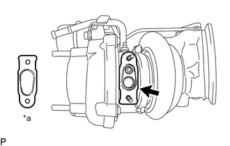
*a NG Install a new inlet turbo oil gasket to the turbocharger sub-assembly as shown in the illustration.
Note
Make sure that the inlet turbo oil gasket is installed in the correct direction.
-
Install the inlet turbo oil pipe sub-assembly to the turbocharger sub-assembly with the 2 nuts.
- Torque:
- 12 N*m { 122 kgf*cm, 9 ft.*lbf }
-
-
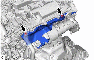
INSTALL NO. 1 TURBO WATER PIPE SUB-ASSEMBLY
-
Install a new water by-pass gasket to the turbocharger sub-assembly.
-
Temporarily install the No. 1 turbo water pipe sub-assembly to the turbocharger sub-assembly with the bolt and 2 nuts.
-
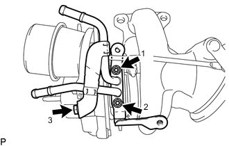
Tighten the bolt and 2 nuts in the order shown in the illustration.
- Torque:
- 12 N*m { 122 kgf*cm, 9 ft.*lbf }
-
-
INSTALL INLET COMPRESSOR ELBOW
-
INSTALL NO. 3 TURBO WATER HOSE
-
Install the No. 3 turbo water hose to the No. 1 turbo water pipe sub-assembly and slide the clip to secure it.
-
-
INSTALL NO. 4 TURBO WATER HOSE
-
Install the No. 4 turbo water hose to the No. 1 turbo water pipe sub-assembly and slide the clip to secure it.
-
-
INSTALL TURBOCHARGER SUB-ASSEMBLY
-
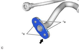
*a Claw Install a new outlet No. 1 turbo oil gasket to the inlet turbo oil pipe sub-assembly as shown in the illustration.
Note
Make sure that the claws of the outlet No. 1 turbo oil gasket are facing the inlet turbo oil pipe sub-assembly.
-
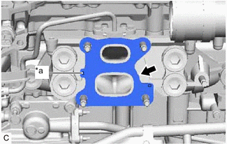
*a Protrusion Install a new exhaust manifold to head gasket to the cylinder head sub-assembly.
Note
Make sure that the protrusion of the exhaust manifold to head gasket is facing the cylinder head sub-assembly as shown in the illustration.
-
Temporarily install the turbocharger sub-assembly to the cylinder head sub-assembly with 4 new nuts.
-
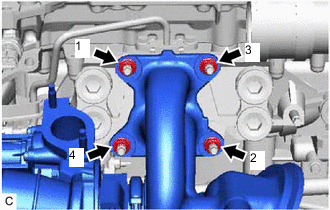
Tighten the 4 nuts in the order shown in the illustration.
- Torque:
- 43 N*m { 438 kgf*cm, 32 ft.*lbf }
-
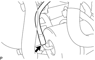
Connect the vacuum transmitting hose assembly to the waste gate valve actuator with bracket assembly.
Note
Make sure that the vacuum transmitting hose assembly is installed all the way to the bent portion of the pipe of the waste gate valve actuator.
-
Connect the intake air control valve (air by-pass valve assembly) connector.
-
Engage the wire harness clamp.
-
-
CONNECT INLET TURBO OIL PIPE SUB-ASSEMBLY
-
Install a new No. 1 union bolt gasket to the union bolt.
-
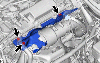
Connect the inlet turbo oil pipe sub-assembly to the cylinder block sub-assembly with the 2 bolts and union bolt.
-
Tighten the 2 bolts and union bolt.
- Torque:
- Bolt
- 10 N*m { 102 kgf*cm, 7 ft.*lbf }
- Union Bolt
- 35 N*m { 357 kgf*cm, 26 ft.*lbf }
Note
If the link that connects the gaskets is broken, remove the link by using side cutters or a similar tool.
-
-
INSTALL HEAT INSULATOR BRACKET
-
Temporarily install the No. 2 heat insulator bracket to the turbocharger sub-assembly and No. 1 heat insulator bracket with the 2 bolts.
-
Temporarily install the No. 1 heat insulator bracket to the cylinder head sub-assembly with the 2 bolts.
-
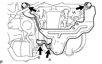
Tighten the 4 bolts in several steps in the order shown in the illustration.
- Torque:
- Bolt (A)
- 21 N*m { 214 kgf*cm, 15 ft.*lbf }
- Bolt (B)
- 10 N*m { 102 kgf*cm, 7 ft.*lbf }
-
-
CONNECT NO. 3 TURBO WATER HOSE
-
Connect the No. 3 turbo water hose to the No. 1 turbo water pipe sub-assembly and slide the clip to secure it.
Note
The turbocharger sub-assembly may be damaged if the No. 3 turbo water hose is connected to the wrong locations.
-
-
CONNECT NO. 4 TURBO WATER HOSE
-
Connect the No. 4 turbo water hose to the No. 1 turbo water pipe sub-assembly and slide the clip to secure it.
Note
The turbocharger sub-assembly may be damaged if the No. 4 turbo water hose is connected to the wrong locations.
-
-
INSTALL OUTLET COMPRESSOR ELBOW
-
Install a new outlet compressor gasket to the turbocharger sub-assembly.
-
Install the outlet compressor elbow with intake air resonator to the turbocharger sub-assembly with the 2 nuts.
- Torque:
- 24 N*m { 245 kgf*cm, 18 ft.*lbf }
-
Connect the vacuum transmitting hose assembly to the outlet compressor elbow with the clamp.
-
-
CONNECT NO. 1 AIR TUBE
-
Connect the No. 1 air tube to the intake air resonator.
-
Connect the No. 1 air tube to the cylinder head sub-assembly with the bolt.
- Torque:
- 21 N*m { 214 kgf*cm, 15 ft.*lbf }
-
Tighten the hose clamp.
- Torque:
- 6.3 N*m { 64 kgf*cm, 56 in.*lbf }
-
-
INSTALL NO. 5 EXHAUST MANIFOLD HEAT INSULATOR
-
Type A:
-
Temporarily install the No. 5 exhaust manifold heat insulator with the 3 bolts.
-
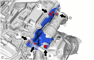
Install the bolt (A).
- Torque:
- 21 N*m { 214 kgf*cm, 15 ft.*lbf }
-
Tighten the 2 bolts (B) and bolt (C).
- Torque:
- Bolt (B)
- 10 N*m { 102 kgf*cm, 7 ft.*lbf }
- Bolt (C)
- 21 N*m { 214 kgf*cm, 15 ft.*lbf }
-
Install the bolt (D).
- Torque:
- 21 N*m { 214 kgf*cm, 15 ft.*lbf }
-
-
Type B:
-
Temporarily install the No. 5 exhaust manifold heat insulator with the 2 bolts.
-
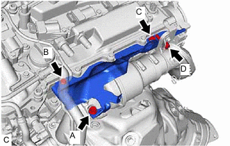
Install the bolt (A).
- Torque:
- 21 N*m { 214 kgf*cm, 15 ft.*lbf }
-
Tighten the bolt (B) and bolt (C).
- Torque:
- Bolt (B)
- 10 N*m { 102 kgf*cm, 7 ft.*lbf }
- Bolt (C)
- 21 N*m { 214 kgf*cm, 15 ft.*lbf }
-
Install the bolt (D).
- Torque:
- 21 N*m { 214 kgf*cm, 15 ft.*lbf }
-
-
-
INSTALL FRONT NO. 1 ENGINE MOUNTING BRACKET LH
-
Install the front No. 1 engine mounting bracket LH to the cylinder block sub-assembly with the 4 bolts.
- Torque:
- 43 N*m { 438 kgf*cm, 32 ft.*lbf }
-
Connect the front engine mounting insulator to the engine assembly with the bolt.
- Torque:
- 35 N*m { 357 kgf*cm, 26 ft.*lbf }
-
-
INSTALL FRONT ENGINE MOUNTING HEAT INSULATOR LH (w/ Front Engine Mounting Heat Insulator LH)
-
INSPECT WASTE GATE VALVE ACTUATOR WITH BRACKET ASSEMBLY
-
INSTALL EXHAUST MANIFOLD CONVERTER SUB-ASSEMBLY (TWC: Front and Rear Catalyst)