TURBOCHARGER DISASSEMBLY
PROCEDURE
-
REMOVE WASTE GATE VALVE ACTUATOR WITH BRACKET ASSEMBLY
Note
After removal and installation of the waste gate valve actuator with bracket assembly, make sure to check the travel of the waste gate valve actuator.
-
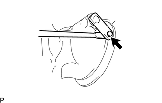
Remove the E-washer from the waste gate valve actuator with bracket assembly link pin.
Note
Do not reuse the E-washer.
-
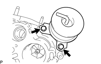
Remove the 2 bolts and waste gate valve actuator with bracket assembly.
Note
Do not drop or subject any component of the turbocharger sub-assembly to impact. If any component of the turbocharger sub-assembly is dropped or subjected to a strong impact, replace it with a new one.
Tech Tips
Adjustment washers may be installed between the waste gate valve actuator with bracket assembly and compressor housing with bearing sub-assembly.
-
-
REMOVE INTAKE AIR CONTROL VALVE (AIR BY-PASS VALVE ASSEMBLY)
-
REMOVE COMPRESSOR HOUSING WITH BEARING SUB-ASSEMBLY
-
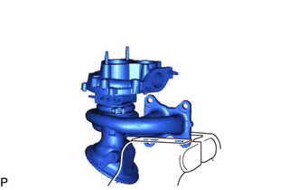
Secure the flange of the turbine housing with valve sub-assembly of the turbocharger sub-assembly in a vise between aluminum plates.
Note
Do not tighten the vise more than necessary, as doing so may damage the flange of the turbine housing with valve sub-assembly.
-
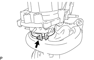
Remove the V band, nut and compressor housing with bearing sub-assembly.
Note
-
Do not damage the turbine housing with valve sub-assembly and turbine.
-
Do not drop or subject any component of the turbocharger sub-assembly to impact. If any component of the turbocharger sub-assembly is dropped or subjected to a strong impact, replace it with a new one.
-
Do not tap or subject the compressor housing with bearing sub-assembly to any impact.
-
Do not attempt to pry components with a screwdriver or similar tool.
-
-
-
REMOVE STUD BOLT
Tech Tips
Replace the stud bolt if it is deformed or its threads are damaged.
-
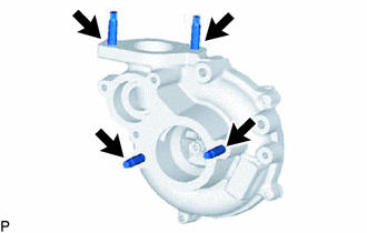
Using an E8 "TORX" socket wrench, remove the 4 stud bolts shown in the illustration.
-
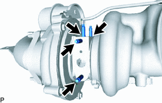
Using an E5 "TORX" socket wrench, remove the 4 stud bolts shown in the illustration.
-
-
REMOVE PIN
Tech Tips
Replace the pin if it is deformed or damaged.
-
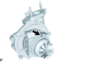
Remove the pin shown in the illustration from the compressor housing with bearing sub-assembly.
-