INTAKE AIR CONTROL VALVE INSTALLATION
PROCEDURE
-
INSTALL INTAKE AIR CONTROL VALVE (AIR BY-PASS VALVE ASSEMBLY)
-
Using a T30 "TORX" socket wrench, install the intake air control valve (air by-pass valve assembly) with the 3 bolts.
- Torque:
- 8.5 N*m { 87 kgf*cm, 75 in.*lbf }
-
-
CONNECT ENGINE WIRE
-
Install the 2 nuts.
- Torque:
- 10 N*m { 102 kgf*cm, 7 ft.*lbf }
-
Engage the clamp.
-
Connect the engine coolant temperature sensor connector.
-
Connect the camshaft timing oil control solenoid assembly connector.
-
Install the nut.
- Torque:
- 10 N*m { 102 kgf*cm, 7 ft.*lbf }
-
Connect the intake air control valve (air by-pass valve assembly) connector.
-
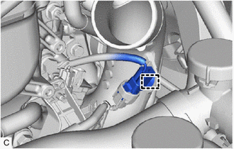
Engage the clamp.
-
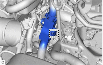
Connect the connector and install the bolt.
- Torque:
- 10 N*m { 102 kgf*cm, 7 ft.*lbf }
-
Engage the clamp.
-
Connect the ECM connector and lower the lever.
Note
-
When connecting the ECM connector, make sure that the connecting parts of the ECM connector are free of dirt, water or other foreign matter.
-
Be sure to securely connect the ECM connector.
-
-
-
INSTALL AIR CLEANER HOSE ASSEMBLY
-
Align the cutout of the air cleaner hose assembly with the protrusion of the air cleaner cap assembly.
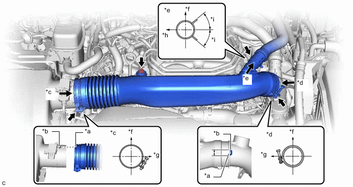
*a Cutout *b Protrusion *c View A *d View B *e View C *f Upper *g Front *h Rear *i 45° - - Tech Tips
Make sure the direction of the clip is as shown in the illustration.
-
Align the cutout of the air cleaner hose assembly with the protrusion of the compressor inlet elbow, and install the air cleaner hose assembly.
Tech Tips
Make sure the direction of the clip is as shown in the illustration.
-
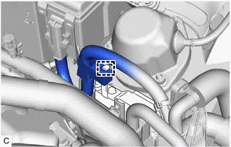
Connect the No. 1 ventilation hose to the air cleaner hose assembly and slide the clip to secure it.
-
Install the bolt.
- Torque:
- 5.0 N*m { 51 kgf*cm, 44 in.*lbf }
-
Tighten the 2 hose clamps to the positions shown in the illustration.
- Torque:
- 4.0 N*m { 41 kgf*cm, 35 in.*lbf }
-
-
INSTALL NO. 1 ENGINE COVER SUB-ASSEMBLY
-
INSTALL ENGINE ROOM ECU COVER
-
CONNECT CABLE TO NEGATIVE BATTERY TERMINAL
Note
When disconnecting the cable, some systems need to be initialized after the cable is reconnected.