INTAKE MANIFOLD INSTALLATION
PROCEDURE
-
INSTALL VACUUM SURGE TANK
-
Install the vacuum surge tank to the intake manifold with the 3 bolts.
- Torque:
- 10 N*m { 102 kgf*cm, 7 ft.*lbf }
-
-
INSTALL NO. 4 VACUUM TRANSMITTING HOSE ASSEMBLY
-
Install the No. 4 vacuum transmitting hose assembly to the vacuum surge tank and engage the 2 clamps.
-
-
INSTALL VACUUM REGULATING VALVE ASSEMBLY
-
Install the vacuum regulating valve assembly to the intake manifold with the 2 bolts.
- Torque:
- 10 N*m { 102 kgf*cm, 7 ft.*lbf }
-
-
INSTALL NO. 1 TURBO PRESSURE SENSOR
-
Install the No. 1 turbo pressure sensor to the intake manifold with the bolt.
- Torque:
- 9.0 N*m { 92 kgf*cm, 80 in.*lbf }
-
-
INSTALL NO. 3 VACUUM TRANSMITTING HOSE ASSEMBLY
-
Install the No. 3 vacuum transmitting hose assembly to the vacuum surge tank and vacuum regulating valve assembly.
-
Engage the 2 clamps.
-
-
INSTALL BRACKET
-
Install the bracket to the intake manifold with the bolt.
- Torque:
- 10 N*m { 102 kgf*cm, 7 ft.*lbf }
-
-
INSTALL NO. 2 FUEL VAPOR FEED HOSE
-
Install the No. 2 fuel vapor feed hose to the intake manifold and slide the clip to secure it.
-
-
INSTALL NO. 2 TURBO PRESSURE SENSOR
-
Install the No. 2 turbo pressure sensor to the intake manifold with the bolt.
- Torque:
- 10 N*m { 102 kgf*cm, 7 ft.*lbf }
-
Engage the No. 1 vacuum transmitting hose assembly to the intake manifold.
-
-
TEMPORARILY INSTALL INTERCOOLER ASSEMBLY
Note
If temporary installation is not performed, parts may not be correctly positioned. As a result, connecting parts may not be airtight.
-
Temporarily install the intercooler support bracket sub-assembly to the intake manifold with the 2 bolts.
-
Temporarily install the intercooler assembly to the intercooler support bracket sub-assembly with the 3 bolts.
-
Temporarily install the throttle body with motor assembly to the intercooler assembly and intake manifold.
-
Tighten the 2 bolts of the intercooler support bracket sub-assembly.
- Torque:
- 10 N*m { 102 kgf*cm, 7 ft.*lbf }
-
Remove the throttle body with motor assembly from the intake manifold.
-
Remove the 3 bolts and intercooler assembly from the intercooler support bracket sub-assembly.
-
-
SET INTERCOOLER ASSEMBLY
-
INSTALL INTAKE MANIFOLD
-
Install the No. 5 water by-pass pipe to the intercooler support bracket sub-assembly with the 2 bolts and nut.
- Torque:
- 10 N*m { 102 kgf*cm, 7 ft.*lbf }
-
Install 2 new intake manifold gaskets to the intake manifold.
-
Temporarily install the intake manifold and intercooler support bracket sub-assembly to the cylinder head sub-assembly and cylinder block sub-assembly with the 4 bolts and 2 nuts.
-
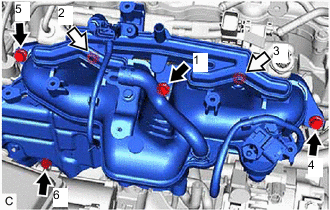

Bolt 
Nut Tighten the 4 bolts and 2 nuts in the order shown in the illustration.
- Torque:
- 21 N*m { 214 kgf*cm, 15 ft.*lbf }
-
-
CONNECT INLET HEATER WATER HOSE B
-
Connect the inlet heater water hose B to the No. 5 water by-pass pipe and slide the clip to secure it.
-
-
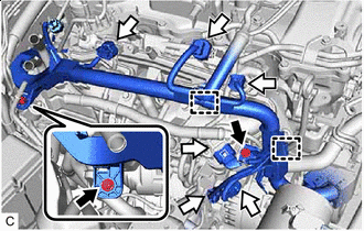
CONNECT VACUUM TRANSMITTING HOSE ASSEMBLY
-
Engage the 4 clamps and connect the vacuum transmitting hose assembly to the cylinder head cover sub-assembly.
-
Connect the vacuum transmitting hose assembly to the waste gate valve actuator with bracket assembly.
Note
Connect the vacuum transmitting hose assembly until the bent portion of the pipe of the waste gate valve actuator with bracket assembly.
-
-
CONNECT NO. 2 VACUUM TRANSMITTING HOSE ASSEMBLY
-
Connect the No. 2 vacuum transmitting hose assembly to the vacuum pump assembly.
-
Engage the clamp to the cylinder head cover sub-assembly.
-
-
CONNECT NO. 3 WATER BY-PASS HOSE
-
Connect the No. 3 water by-pass hose to the water outlet sub-assembly and slide the clip to secure it.
-
Engage the clamp.
-
-
CONNECT ENGINE WIRE
-
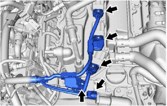
Connect the 5 connectors.
-
Bolt Connector Engage the 2 clamps.
-
Connect the 6 connectors.
-
Install the 2 bolts.
- Torque:
- 10 N*m { 102 kgf*cm, 7 ft.*lbf }
-
-
CONNECT OUTLET HEATER WATER HOSE A
-
CONNECT INLET HEATER WATER HOSE A
-
INSTALL NO. 2 WATER BY-PASS PIPE
-
Install the No. 2 water by-pass pipe to the intake manifold with the 2 bolts.
- Torque:
- 10 N*m { 102 kgf*cm, 7 ft.*lbf }
-
Connect the No. 2 turbo water hose and No. 1 turbo water hose to the No. 2 water by-pass pipe and slide the 2 clips to secure them.
-
-
INSTALL NO. 2 VENTILATION HOSE
-
Install the No. 2 ventilation hose to the intake manifold and cylinder head cover sub-assembly and slide the 2 clips to secure them.
-
-
INSTALL FUEL HOSE BRACKET
-
Install the fuel hose bracket to the intake manifold with the bolt.
- Torque:
- 10 N*m { 102 kgf*cm, 7 ft.*lbf }
-
Engage the 2 fuel tube sub-assemblies to the fuel hose bracket.
-
Engage the clamp
-
-
INSTALL AIR CLEANER HOSE ASSEMBLY
-
INSTALL NO. 1 ENGINE COVER SUB-ASSEMBLY
-
INSTALL INTERCOOLER RESERVE TANK ASSEMBLY
-
Connect the No. 4 intercooler cooling water hose to the intercooler reserve tank assembly and slide the clip to secure it.
-
Install the intercooler reserve tank assembly to the intercooler reserve tank bracket with the 2 bolts.
- Torque:
- 12.5 N*m { 127 kgf*cm, 9 ft.*lbf }
-
Connect the No. 3 intercooler cooling water hose to the No. 2 water by-pass pipe and slide the clip to secure it.
-
Engage the 2 fuel tube sub-assemblies to the intercooler reserve tank assembly.
-
-
INSTALL PURGE VALVE (PURGE VSV)
-
w/ Canister Pump Module:
-
w/o Canister Pump Module:
-
-
INSTALL INTERCOOLER ASSEMBLY
-
CONNECT NO. 1 AIR TUBE
-
CONNECT ENGINE WIRE
-
INSTALL HEATER WATER PUMP ASSEMBLY
-
CONNECT NO. 9 WATER BY-PASS HOSE
-
CONNECT NO. 8 WATER BY-PASS HOSE
-
CONNECT NO. 1 VACUUM TRANSMITTING HOSE
-
CONNECT NO. 2 TURBO WATER HOSE
-
INSTALL THROTTLE BODY WITH MOTOR ASSEMBLY