MONOLITHIC CONVERTER INSTALLATION
PROCEDURE
-
INSTALL STUD BOLT
Note
If a stud bolt is deformed or its threads are damaged, replace it.
-
Using an E10 "TORX" socket wrench, install the stud bolt to the exhaust manifold converter sub-assembly (TWC: Front and Rear Catalyst).
- Torque:
- 14.5 N*m { 148 kgf*cm, 11 ft.*lbf }
-
-
INSTALL EXHAUST MANIFOLD CONVERTER SUB-ASSEMBLY (TWC: Front and Rear Catalyst)
-
Set a new exhaust pipe clamp to the turbocharger sub-assembly.
Note
Do not open the exhaust pipe clamp more than 140 mm (5.51 in.). The standard required opening should be approximately 60 mm (2.36 in.).
-
Temporarily install the turbocharger stay to the exhaust manifold converter sub-assembly (TWC: Front and Rear Catalyst) with the nut.
Note
Tighten the nut by hand until it contacts the surface of the turbocharger stay.
-
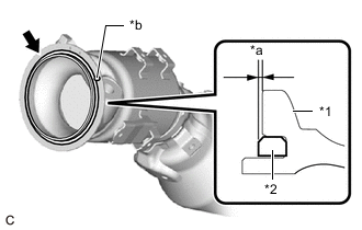
*1 Exhaust Manifold Converter Sub-assembly (TWC: Front and Rear Catalyst) *2 Outlet Turbine Elbow Gasket *a 1.5 mm (0.0591 in.) or less *b Knock Pin Install a new outlet turbine elbow gasket to the exhaust manifold converter sub-assembly (TWC: Front and Rear Catalyst) as shown in the illustration.
Note
When reusing the exhaust manifold converter sub-assembly (TWC: Front and Rear Catalyst), thoroughly clean the gasket groove.
Tech Tips
Make sure that the outlet turbine elbow gasket is securely installed into the gasket groove of the exhaust manifold converter sub-assembly (TWC: Front and Rear Catalyst).
-
Temporarily install the turbocharger stay to the stud bolt on the cylinder head sub-assembly side with the nut.
Note
Tighten the nut by hand until it contacts the surface of the turbocharger stay.
-
While aligning the knock pin of the exhaust manifold converter sub-assembly (TWC: Front and Rear Catalyst) with the pin hole on the turbocharger sub-assembly, set the exhaust manifold converter sub-assembly (TWC: Front and Rear Catalyst) to the turbocharger sub-assembly.
-
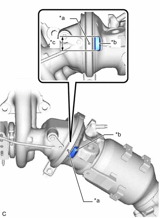
*a Protrusion on Exhaust Pipe Clamp Side *b Protrusion on Exhaust Manifold Converter Sub-assembly (TWC: Front and Rear Catalyst) Side *c Alignment Area While aligning the protrusion of the exhaust pipe clamp as shown in the illustration, temporarily install the exhaust pipe clamp.
-
Tighten the exhaust pipe clamp.
- Torque:
- 25 N*m { 255 kgf*cm, 18 ft.*lbf }
-
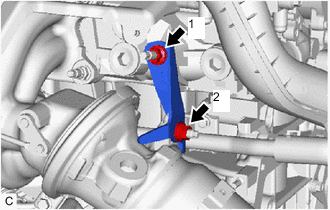
Tighten the 2 nuts in the order shown in the illustration.
- Torque:
- 43 N*m { 438 kgf*cm, 32 ft.*lbf }
-
-
INSTALL NO. 2 EXHAUST MANIFOLD HEAT INSULATOR
-
Install the No. 2 exhaust manifold heat insulator to the exhaust manifold converter sub-assembly (TWC: Front and Rear Catalyst) with the 4 bolts.
- Torque:
- 10 N*m { 102 kgf*cm, 7 ft.*lbf }
-
-
INSTALL NO. 4 EXHAUST MANIFOLD HEAT INSULATOR
-
Install the No. 4 exhaust manifold heat insulator to the exhaust manifold converter sub-assembly (TWC: Front and Rear Catalyst) and turbocharger sub-assembly with the 3 bolts.
- Torque:
- 10 N*m { 102 kgf*cm, 7 ft.*lbf }
-
-
INSTALL NO. 1 EXHAUST MANIFOLD HEAT INSULATOR
-
Install the No. 1 exhaust manifold heat insulator to the No. 1 heat insulator bracket and exhaust manifold converter sub-assembly (TWC: Front and Rear Catalyst) with the 5 bolts.
- Torque:
- 10 N*m { 102 kgf*cm, 7 ft.*lbf }
-
-
INSTALL AIR FUEL RATIO SENSOR