FUEL SENDER GAUGE ASSEMBLY(w/ Canister Pump Module) INSTALLATION

PROCEDURE
-
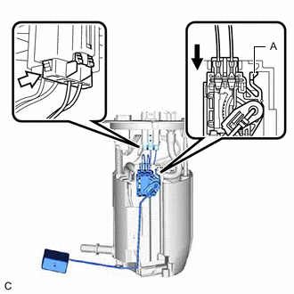
INSTALL NO. 2 FUEL SENDER GAUGE ASSEMBLY
-
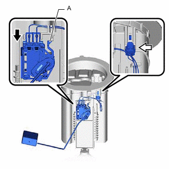

Slide Slide the No. 2 fuel sender gauge assembly downward and engage the claw (A) to install the No. 2 fuel sender gauge assembly.
Note
-
Do not touch the resistance plate or contacts of the No. 2 fuel sender gauge assembly.
-
Be careful not to bend the arm of the No. 2 fuel sender gauge assembly.
-
-
Connect the No. 2 fuel sender gauge assembly connector.
-
-
INSTALL FUEL TANK VENT TUBE ASSEMBLY
-
Install a new fuel suction tube set gasket to the fuel tank assembly.
-
Connect the fuel return vent tube sub-assembly and set the fuel tank vent tube assembly on the fuel tank assembly.
Note
-
Be careful not to bend the arm of the No. 2 fuel sender gauge assembly.
-
Do not damage the fuel return vent tube sub-assembly.
-
When connecting the fuel tube connector, do not excessively pull on the fuel return vent tube sub-assembly.
-
-
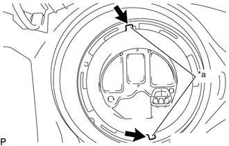
*a Protrusion Notch Align the protrusions of the fuel tank vent tube assembly with the notches in the fuel tank assembly.
-
While pressing down on the fuel tank vent tube assembly, temporarily install the fuel pump gauge retainer.
-
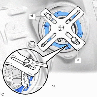
*a Insertion Point *b SST (Plate) *c SST (Claw) *d SST (Bolt) Temporarily install SST (plate) and SST (claw) to the fuel pump gauge retainer.
- SST
- 09808-14031 ( 09808-01030, 09808-01050 )
- 09808-01071
Tech Tips
Securely insert the ends of SST (claw) into the insertion points in the fuel pump gauge retainer.
-
While firmly pressing SST (claw) into the insertion points in the fuel pump gauge retainer, tighten SST (bolt).
-
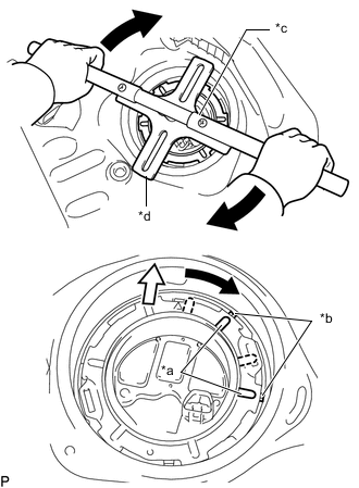
*a Protrusion *b Groove *c SST (Handle) *d SST (Plate) 
Front Side Install SST (handle) to SST (plate).
- SST
- 09808-14031 ( 09808-01010, 09808-01030, 09808-01050 )
- 09808-01071
-
Using SST, rotate the fuel pump gauge retainer so that the protrusions of the fuel pump gauge retainer are aligned with the grooves in the fuel tank assembly to install the fuel pump gauge retainer to the fuel tank assembly.
Note
-
Do not use any tools other than specified as this may result in damage to the fuel pump gauge retainer or the fuel tank assembly.
-
Do not press down on SST excessively as this may make the fuel pump gauge retainer hard to rotate, and may damage components.
-
Make sure to rotate SST (handle) horizontally. If it is rotated at an angle, SST may come off.
-
Do not spin SST too fast or use an impact wrench as this may result in damage to components.
-
If SST comes off of the fuel pump gauge retainer, loosen SST (bolt) and reinstall SST.
-
Make sure that the fuel suction tube set gasket does not come off.
-
-
Install the No. 1 fuel tube clamp.
-
-
INSTALL REAR FLOOR SERVICE HOLE COVER
-
Remove any remaining butyl tape from the rear floor service hole cover and vehicle body.
-
Clean the installation surfaces of the rear floor service hole cover and vehicle body.
-
Connect the fuel tank vent tube assembly connector.
-
Install the rear floor service hole cover with new butyl tape.
-
-
INSTALL FUEL SENDER GAUGE ASSEMBLY
-
Slide Slide the fuel sender gauge assembly downward and engage the claw (A) to install the fuel sender gauge assembly.
Note
-
Do not touch the resistance plate or contacts of the fuel sender gauge assembly.
-
Be careful not to bend the arm of the fuel sender gauge assembly.
-
-
Connect the fuel sender gauge assembly connector.
-
-
INSTALL FRONT QUARTER TRIM PANEL ASSEMBLY RH
-
INSTALL REAR SIDE SEATBACK ASSEMBLY RH
-
CONNECT REAR SEAT 3 POINT TYPE OUTER BELT ASSEMBLY RH
-
INSTALL FRONT DOOR SCUFF PLATE RH
-
INSTALL FUEL SUCTION TUBE WITH PUMP AND GAUGE ASSEMBLY