FUEL INJECTOR(for Port Injection) INSTALLATION

PROCEDURE
-
INSTALL FUEL INJECTOR ASSEMBLY
Tech Tips
Perform "Inspection After Repair" after replacing a fuel injector assembly.
-
w/ Canister Pump Module:
-
w/o Canister Pump Module:
-
for Bank 1:
-
Apply a light coat of spindle oil or gasoline to 3 new O-rings, and install 1 to each fuel injector assembly.
Note
Check that there is no damage or foreign matter on the groove of the fuel injector assembly when installing the O-ring to each fuel injector assembly.
-
Connect the 3 fuel injector assembly connectors.
-
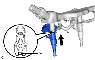
*a Stopper Install the 3 fuel injector assemblies to the fuel delivery pipe with sensor assembly.
Note
-
Make sure that the fuel injector assembly is located within the stopper as shown in the illustration.
-
Check that the fuel injector assembly installation holes of the fuel delivery pipe with sensor assembly are not damaged and are free of foreign matter.
-
Make sure that the O-ring is not damaged, twisted or moved out of place when installing the fuel injector assembly.
-
-
-
for Bank 2:
-
Apply a light coat of spindle oil or gasoline to 3 new O-rings, and install 1 to each fuel injector assembly.
Note
Check that there is no damage or foreign matter on the groove of the fuel injector assembly when installing the O-ring to each fuel injector assembly.
-
Connect the 3 fuel injector assembly connectors.
-
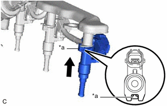
*a Stopper Install the 3 fuel injector assemblies to the fuel delivery pipe with sensor assembly.
Note
-
Make sure that the fuel injector assembly is located within the stopper as shown in the illustration.
-
Check that the fuel injector assembly installation holes of the fuel delivery pipe with sensor assembly are not damaged and are free of foreign matter.
-
Make sure that the O-ring is not damaged, twisted or moved out of place when installing the fuel injector assembly.
-
-
-
-
INSTALL FUEL DELIVERY PIPE WITH SENSOR ASSEMBLY
Note
-
Do not remove the fuel pressure sensor from the fuel delivery pipe with sensor assembly.
-
If the fuel pressure sensor is removed, replace the fuel pressure sensor (fuel delivery pipe with sensor assembly) with a new one.
-
Install 6 new injection vibration insulators to the intake manifold.
-
Install the 4 No. 1 delivery pipe spacers to the intake manifold.
-
Install the fuel delivery pipe with sensor assembly (with fuel injector assembly) to the intake manifold.
Note
Be careful not to twist the O-ring.
-
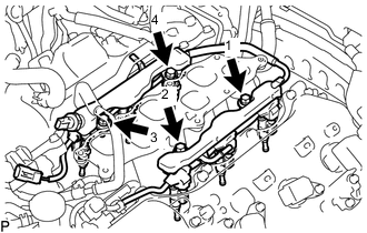
Install the fuel delivery pipe with sensor assembly with the fuel injector assemblies to the intake manifold with the 4 bolts in the order shown in the illustration.
- Torque:
- 17 N*m { 173 kgf*cm, 13 ft.*lbf }
-
-
CONNECT WIRE HARNESS
-
for Bank 2:
-
Engage the claw and connect the No. 8 engine wire to the No. 7 engine wire.
-
Engage the clamp.
-
Engage the claw and connect the No. 7 engine wire to the cylinder head cover sub-assembly LH.
-
-
for Bank 1:
-
Engage the claw and connect the No. 5 engine wire to the No. 6 engine wire.
-
Engage the claw and connect the No. 6 engine wire to the cylinder head cover sub-assembly.
-
-
Connect the No. 5 engine wire connector, No. 6 engine wire connector, No. 7 engine wire connector, No. 8 engine wire connector and fuel pressure sensor connector.
-
-
INSTALL NO. 1 FUEL TUBE SUB-ASSEMBLY
-
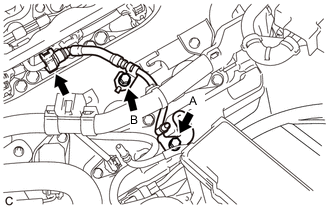
Connect the No. 1 fuel tube sub-assembly to the fuel delivery pipe with sensor assembly.
-
Install the No. 1 fuel tube sub-assembly with the 2 bolts.
- Torque:
- for Bolt (A)
- 10 N*m { 102 kgf*cm, 7 ft.*lbf }
- for Bolt (B)
- 20 N*m { 204 kgf*cm, 15 ft.*lbf }
-
-
INSTALL NO. 1 ENGINE COVER SUB-ASSEMBLY
-
Install the No. 1 engine cover sub-assembly with the clip.
-
-
INSTALL NO. 2 FUEL TUBE SUB-ASSEMBLY
-
Install the No. 2 fuel tube sub-assembly to the fuel pipe.
-
Install the fuel hose protector to the fuel tube connector.
-
Engage the claw to close the cover of the fuel hose protector.
-
Connect the No. 2 fuel tube sub-assembly to the fuel pipe.
-
Engage the claw to close the cover of the No. 1 fuel pipe clamp.
-
-
INSTALL INTAKE AIR SURGE TANK ASSEMBLY
-
CONNECT CABLE TO NEGATIVE BATTERY TERMINAL
Note
When disconnecting the cable, some systems need to be initialized after the cable is reconnected.
-
INSPECT FOR FUEL LEAK
-
PERFORM INITIALIZATION
-
Perform "Inspection After Repair" after replacing a fuel injector assembly.
-
w/ Canister Pump Module:
-
w/o Canister Pump Module:
-
-