FUEL SENDER GAUGE ASSEMBLY(w/o Canister Pump Module) REMOVAL

PROCEDURE
-
REMOVE FUEL SUCTION TUBE WITH PUMP AND GAUGE ASSEMBLY
-
REMOVE FRONT DOOR SCUFF PLATE RH
-
DISCONNECT REAR SEAT 3 POINT TYPE OUTER BELT ASSEMBLY RH
-
REMOVE REAR SIDE SEATBACK ASSEMBLY RH
-
REMOVE FRONT QUARTER TRIM PANEL ASSEMBLY RH
-
REMOVE FUEL SENDER GAUGE ASSEMBLY
-
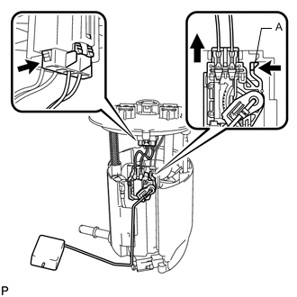
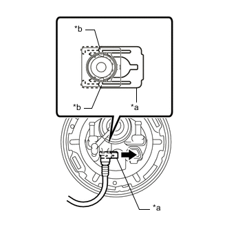
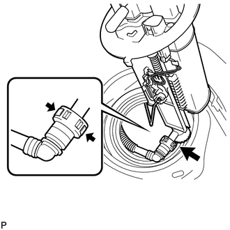
Disconnect the fuel sender gauge assembly connector.
-
Push the claw (A) of the fuel sender gauge assembly, and then pull up the fuel sender gauge assembly to remove it.
Note
-
Do not touch the resistance plate or contacts of the fuel sender gauge assembly.
-
Make sure that the fuel sender gauge assembly arm does not bend.
-
-
-
REMOVE REAR FLOOR SERVICE HOLE COVER
-
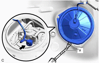
*a Protective Tape Remove the rear floor service hole cover and butyl tape.
-
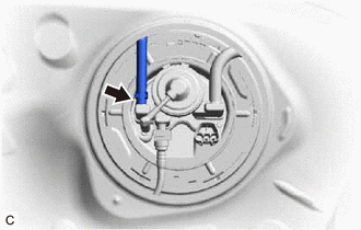
Disconnect the No. 2 fuel sender gauge assembly connector.
-
-
REMOVE FUEL TANK VENT TUBE ASSEMBLY
-
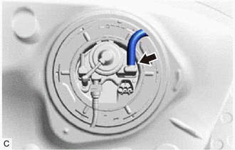
Slide the clip and disconnect the No. 1 fuel evaporation tube sub-assembly from the fuel tank vent tube assembly.
-
Disconnect the charcoal canister outlet hose from the fuel tank vent tube assembly.
-
*a Retainer *b Claw 
Pull Disengage the 2 claws of the retainer. Release the retainer and disconnect the fuel tank EVAP/VENT tube from the fuel tank vent tube assembly.
-
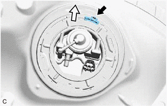

Front Side Release the lock and remove the No. 1 fuel tube clamp.
-
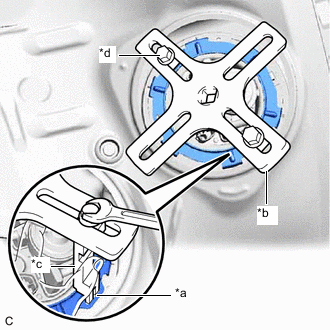
*a Insertion Point *b SST (Plate) *c SST (Claw) *d SST (Bolt) Temporarily install SST (plate) and SST (claw) to the fuel pump gauge retainer.
- SST
- 09808-14030 ( 09808-01030, 09808-01050 )
- 09808-01071
Tech Tips
Securely insert the ends of SST (claw) into the insertion points in the fuel pump gauge retainer.
-
While firmly pressing SST (claw) into the insertion points in the fuel pump gauge retainer, tighten SST (bolt).
-
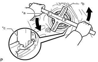
*a SST (Handle) *b SST (Plate) *c SST (Claw) Install SST (handle) to SST (plate).
- SST
- 09808-14030 ( 09808-01010, 09808-01030, 09808-01050 )
- 09808-01071
-
Lightly press down on SST to prevent it from separating from the fuel pump gauge retainer. While pressing down on SST, rotate SST (handle) slowly to loosen the fuel pump gauge retainer.
Note
-
Do not use any tools other than specified as this may result in damage to the fuel pump gauge retainer or the fuel tank assembly.
-
Do not press down on SST excessively as this may make the fuel pump gauge retainer hard to rotate, and may damage components.
-
Make sure to rotate SST (handle) horizontally. If it is rotated at an angle, SST may come off.
-
Do not spin SST too fast or use an impact wrench as this may result in damage to components.
-
If SST comes off of the fuel pump gauge retainer, loosen SST (bolt) and reinstall SST.
-
-
While pressing down on the fuel tank vent tube assembly, remove the fuel pump gauge retainer.
-
Disconnect the fuel return vent tube sub-assembly and remove the fuel tank vent tube assembly from the fuel tank assembly.
Note
-
Make sure that the No. 2 fuel sender gauge assembly arm does not bend.
-
Do not damage the fuel return vent tube sub-assembly.
-
When disconnecting the fuel tube connector, do not excessively pull on the fuel return vent tube sub-assembly.
-
-
Remove the fuel suction tube set gasket from the fuel tank assembly.
-
-
REMOVE NO. 2 FUEL SENDER GAUGE ASSEMBLY
-
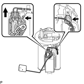
Disconnect the No. 2 fuel sender gauge assembly connector.
-
Push the claw (A) of the No. 2 fuel sender gauge assembly, and then pull up the No. 2 fuel sender gauge assembly to remove it.
Note
-
Do not touch the resistance plate or contacts of the No. 2 fuel sender gauge assembly.
-
Make sure that the No. 2 fuel sender gauge assembly arm does not bend.
-
-