FUEL PUMP(for High Pressure) INSTALLATION
PROCEDURE
-
INSTALL NO. 2 FUEL PIPE SUB-ASSEMBLY
-
Install a new O-ring, new No. 1 back-up ring, new No. 2 back-up ring, new No. 3 back-up ring and new E-ring to the No. 2 fuel pipe sub-assembly as shown in the illustration.
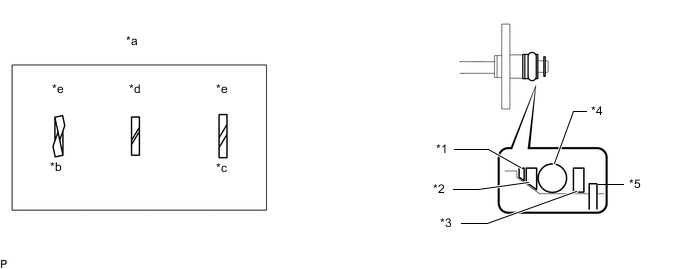
*1 No. 1 Back-up Ring *2 No. 2 Back-up Ring *3 No. 3 Back-up Ring *4 O-ring *5 E-ring - - *a Alignment Opening *b Overlapped *c Stretched *d Correct *e Incorrect - - Note
-
Check that there is no foreign matter or damage on the O-ring groove of the No. 2 fuel pipe sub-assembly.
-
Check that the No. 1 back-up ring and No. 2 back-up ring are installed in the correct orientation.
-
Make sure that the No. 1 back-up ring, No. 2 back-up ring, No. 3 back-up ring and O-ring are installed in the correct order.
-
Check that the alignment openings of the No. 1 back-up ring, No. 2 back-up ring and No. 3 back-up ring are not overlapped or stretched as shown in the illustration.
-
After installing the O-ring, check that it is not contaminated with foreign matter and is not damaged.
-
Check that the No. 2 fuel pipe sub-assembly installation end is not contaminated with foreign matter and is not damaged.
-
-
Apply gasoline to the O-ring and install the No. 2 fuel pipe sub-assembly to the fuel delivery pipe sub-assembly.
Note
-
Do not install the No. 2 fuel pipe sub-assembly at an angle.
-
Do not install the bolt at this time.
-
-
-
INSTALL FUEL PUMP ASSEMBLY
Tech Tips
Perform "Inspection After Repair" after replacing the fuel pump assembly (w/ Canister Pump Module).
-
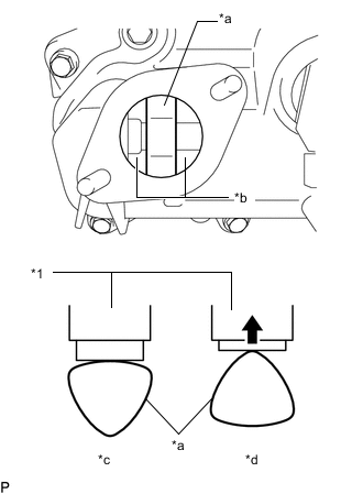
*1 Fuel Pump Assembly *a Cam Lobe *b Oil Collector *c Correct *d Incorrect Turn the crankshaft pulley until the flat of the cam lobe faces the fuel pump assembly installation hole of the cylinder head cover sub-assembly as shown in the illustration.
Tech Tips
This prevent the cam nose from pushing up the pump lifter when installing the fuel pump assembly.
-
Pour 30 cc (1.8 cu in.) of engine oil into the oil collector of the cylinder head cover sub-assembly through the fuel pump assembly installation hole of the cylinder head cover sub-assembly.
-
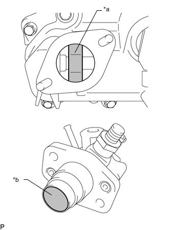
*a Cam Lobe *b Pump Lifter Apply a coat of engine oil to the cam lobe and pump lifter.
-
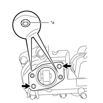
*a Metal Eyelets 
Stud Bolt Install a new fuel pump insulator to the cylinder head cover sub-assembly. Then pass the 2 stud bolts through the holes of the fuel pump assembly and fuel pump insulator.
Note
Install the fuel pump insulator so that the open sides of the metal eyelets are facing outward as shown in the illustration.
-
Temporarily install the No. 2 fuel pipe sub-assembly to the fuel pump assembly.
Note
Be careful not to damage the sealing surface of the No. 2 fuel pipe sub-assembly when temporarily installing the No. 2 fuel pipe sub-assembly.
-
Install and tighten the 2 nuts in several steps.
- Torque:
- 25 N*m { 255 kgf*cm, 18 ft.*lbf }
-
-
CONNECT NO. 2 FUEL PIPE SUB-ASSEMBLY
-
Install the No. 2 fuel pipe sub-assembly to the fuel delivery pipe sub-assembly with the 2 bolts.
- Torque:
- 10 N*m { 102 kgf*cm, 7 ft.*lbf }
-
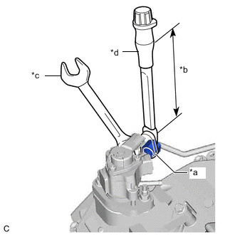
*a 19 mm Union Nut Wrench *b Torque Wrench Fulcrum Length *c Hold *d Turn Using a 21 mm wrench, secure the union bolt on the fuel pump assembly side in place. Using a 19 mm union nut wrench, tighten the union nut and connect the No. 2 fuel pipe sub-assembly.
- Torque:
- Specified tightening torque
- 30 N*m { 306 kgf*cm, 22 ft.*lbf }
Tech Tips
-
Calculate the torque wrench reading when changing the fulcrum length of the torque wrench.
-
When using a 19 mm union nut wrench (fulcrum length of 30 mm (1.18 in.)) + torque wrench (fulcrum length of 180 mm (7.09 in.)): 26 N*m (265 kgf*cm, 19 ft.*lbf)
-
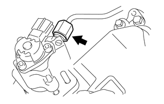
Connect the fuel pump assembly connector.
-
-
INSTALL NO. 1 FUEL PIPE SUB-ASSEMBLY
-
Install the No. 1 fuel pipe sub-assembly with the 2 bolts.
- Torque:
- 10 N*m { 102 kgf*cm, 7 ft.*lbf }
-
Connect the No. 2 fuel hose to the fuel pump assembly and slide the clip to secure it.
-
Connect the No. 1 fuel hose to the fuel relief valve assembly and slide the clip to secure it.
-
Connect the No. 3 fuel hose to the No. 1 fuel pipe sub-assembly and slide the clip to secure it.
-
-
INSTALL FUEL PRESSURE PULSATION DAMPER ASSEMBLY
-
INSTALL NO. 3 WATER BY-PASS PIPE
-
Connect the No. 8 water by-pass hose and No. 9 water by-pass hose to the No. 3 water by-pass pipe and slide the 2 clips to secure them.
-
Install the No. 3 water by-pass pipe to the camshaft housing sub-assembly RH with the bolt.
- Torque:
- 10 N*m { 102 kgf*cm, 7 ft.*lbf }
-
Engage the wire harness clamp to the No. 3 water by-pass pipe.
-
Connect the inlet heater water hose A and outlet heater water hose A to the No. 3 water by-pass pipe and slide the 2 clips to secure them.
-
Install the 2 water hose sets to the inlet heater water hose A and outlet heater water hose A.
-
-
INSTALL INTAKE MANIFOLD
-
CONNECT CABLE TO NEGATIVE BATTERY TERMINAL
Note
When disconnecting the cable, some systems need to be initialized after the cable is reconnected.
-
INSPECT FOR FUEL LEAK
-
PERFORM INITIALIZATION (w/ Canister Pump Module)
-
Perform "Inspection After Repair" after replacing the fuel pump assembly.
-