FUEL INJECTOR(for Direct Injection) INSTALLATION

PROCEDURE
-
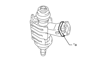
INSTALL FUEL INJECTOR SEAL
-
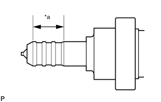
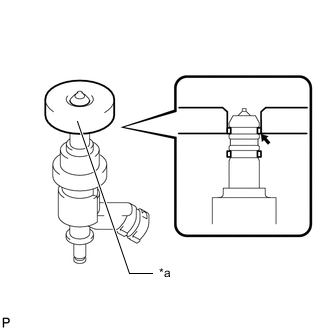
*a Area to be Cleaned Apply engine conditioner to the area shown in the illustration. Using a piece of cloth, clean carbon deposits from the fuel injector assembly and its grooves.
Note
-
Do not clean the tip of the fuel injector assembly.
-
Do not use a wire brush to clean the fuel injector assembly.
-
If a fuel injector assembly is dropped or the tip of a fuel injector assembly is struck, replace it with a new one.
-
-
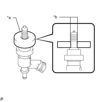
*a SST (Guide) *b Chamfer Apply engine oil to the fuel injector assembly contact surface of SST (guide), then attach SST (guide) to the fuel injector assembly with the chamfer facing the tip of the fuel injector assembly as shown in the illustration.
- SST
- 09260-39015 ( 09268-03020 )
-
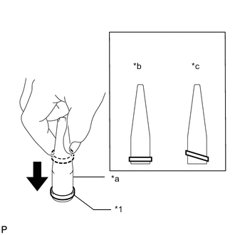
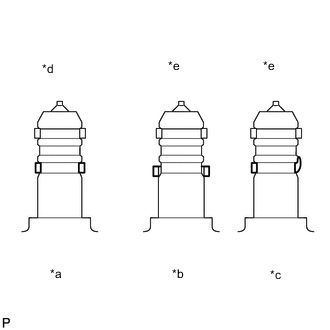
*1 Fuel Injector Seal *a SST (Holder) *b Correct *c Incorrect Install a new fuel injector seal to SST (holder).
- SST
- 09260-39015 ( 09268-03010 )
Note
Be careful not to install the fuel injector seal to SST (holder) at an angle. Doing so will stretch the fuel injector seal.
-
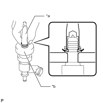
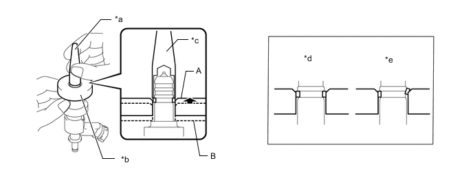
*a SST (Holder) *b SST (Guide) Install SST (holder) with the fuel injector seal to the tip of the fuel injector assembly. Slide the fuel injector seal downward into the fuel injector assembly groove (fuel injector assembly connector side) with your fingers as shown in the illustration.
- SST
- 09260-39015 ( 09268-03010, 09268-03020 )
Tech Tips
Check that the fuel injector seal is seated in the fuel injector assembly groove as shown in the illustration.
-
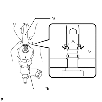
Using SST (holder), gently press downward on the fuel injector seal (fuel injector assembly connector side), then slowly slide SST (guide) toward the fuel injector assembly tip to settle the fuel injector seal into the fuel injector assembly groove.
*a SST (Holder) *b SST (Guide) *c Press gently *d Correct *e Incorrect - - - SST
- 09260-39015 ( 09268-03010, 09268-03020 )
Note
Be sure that the fuel injector seal is not pinched between SST (guide) and the edge of the fuel injector assembly groove. Replace the fuel injector seal if it becomes damaged.
Tech Tips
-
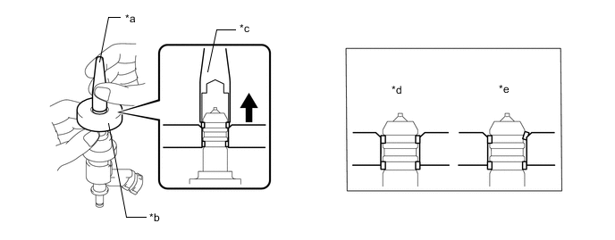
When using SST (guide) to settle the fuel injector seal into the groove, SST (guide) only needs to be slid upward to the position (A) in the illustration.
-
After using SST (guide) to settle the fuel injector seal into the groove, return SST (guide) to the position (B) in the illustration.
-
*1 Fuel Injector Seal *a SST (Holder) *b Correct *c Incorrect Install a new fuel injector seal to SST (holder).
- SST
- 09260-39015 ( 09268-03010 )
Note
Be careful not to install the fuel injector seal to SST (holder) at an angle. Doing so will stretch the fuel injector seal.
-
*a SST (Holder) *b SST (Guide) *c Welded Groove Install SST (holder) with the fuel injector seal to the tip of the fuel injector assembly. Slide the fuel injector seal downward into the fuel injector assembly groove (fuel injector assembly tip side) with your fingers as shown in the illustration.
- SST
- 09260-39015 ( 09268-03010, 09268-03020 )
Note
Make sure that the fuel injector seal does not slip into the welded groove of the fuel injector assembly shown in the illustration. If it does, replace it with a new one.
Tech Tips
Check that the fuel injector seal is seated in the fuel injector assembly groove as shown in the illustration.
-
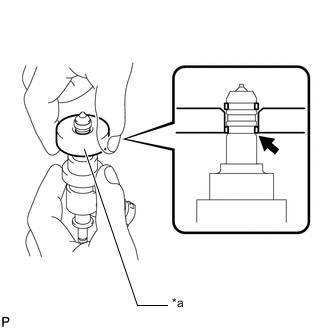
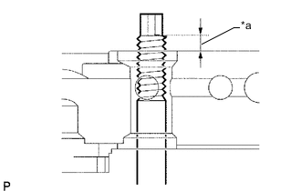
*a SST (Guide) Slowly slide SST (guide) toward the tip of the fuel injector assembly. When the fuel injector assembly contact surface of SST (guide) aligns with the fuel injector seal (fuel injector assembly connector side) as shown in the illustration, hold the position for 5 seconds or more to fully seat the fuel injector seal into the fuel injector assembly groove.
- SST
- 09260-39015 ( 09268-03020 )
Note
Be sure that the fuel injector seal is not pinched between SST (guide) and the edge of the fuel injector assembly groove. Replace the fuel injector seal if it becomes damaged.
Tech Tips
-
Set SST (guide) so that its bottom surface is flush with the fuel injector seal.
-
If it is difficult to slide SST (guide) upward, slowly wiggle it from side to side while sliding it up the fuel injector assembly little by little.
-
Using SST (holder), gently press downward on the fuel injector seal (fuel injector assembly tip side), then slowly slide SST (guide) toward the fuel injector assembly tip to settle the fuel injector seal into the fuel injector assembly groove.
*a SST (Holder) *b SST (Guide) *c Press gently *d Correct *e Incorrect - - - SST
- 09260-39015 ( 09268-03010, 09268-03020 )
Note
Be sure that the fuel injector seal is not pinched between SST (guide) and the edge of the fuel injector assembly groove. Replace the fuel injector seal if it becomes damaged.
-
*a SST (Guide) Slowly slide SST (guide) toward the tip of the fuel injector assembly. When the fuel injector assembly contact surface of SST (guide) aligns with the fuel injector seal (fuel injector assembly tip side) as shown in the illustration, hold the position for 5 seconds or more to fully seat the fuel injector seal into the fuel injector assembly groove.
- SST
- 09260-39015 ( 09268-03020 )
Note
Be sure that the fuel injector seal is not pinched between SST (guide) and the edge of the fuel injector assembly groove. Replace the fuel injector seal if it becomes damaged.
Tech Tips
-
Set SST (guide) so that its bottom surface is flush with the fuel injector seal.
-
If it is difficult to slide SST (guide) upward, slowly wiggle it from side to side while sliding it up the fuel injector assembly little by little.
-
*a Normal *b Protruding *c Deformed *d Correct *e Incorrect After installing the fuel injector seals, check that they are not scratched, deformed or protruding from the fuel injector assembly grooves.
Note
If a fuel injector seal is scratched, deformed or protruding from the groove, replace it with a new one.
-
-
INSTALL FUEL INJECTOR ASSEMBLY
Tech Tips
Perform "Inspection After Repair" after replacing a fuel injector assembly (w/ Canister Pump Module).
-
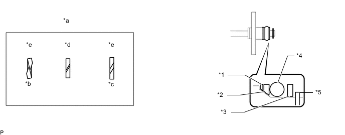
Install a new O-ring, new No. 1 back-up ring, new No. 2 back-up ring, new No. 3 back-up ring and new E-ring to each fuel injector assembly as shown in the illustration.
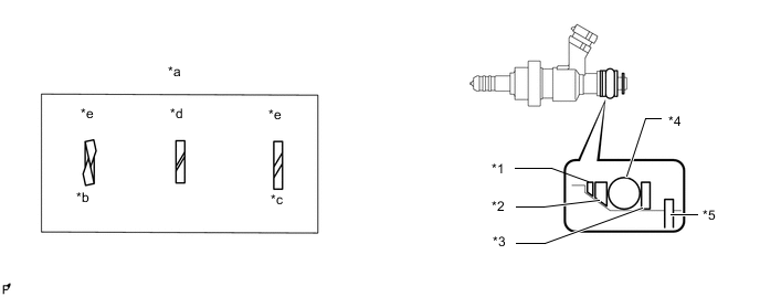
*1 No. 1 Back-up Ring *2 No. 2 Back-up Ring *3 No. 3 Back-up Ring *4 O-ring *5 E-ring - - *a Alignment Opening *b Overlapped *c Stretched *d Correct *e Incorrect - - Note
-
Check that there is no foreign matter or damage on the O-ring groove of the fuel injector assembly.
-
Check that the No. 1 back-up ring and No. 2 back-up ring are installed in the correct orientation.
-
Make sure that the No. 1 back-up ring, No. 2 back-up ring, No. 3 back-up ring and O-ring are installed in the correct order.
-
Check that the alignment openings of the No. 1 back-up ring, No. 2 back-up ring and No. 3 back-up ring are not overlapped or stretched as shown in the illustration.
-
After installing the O-ring, check that it is not contaminated with foreign matter and is not damaged.
-
Check that the end of the fuel injector assembly (fuel delivery pipe assembly and No. 2 fuel delivery pipe assembly side) is not contaminated with foreign matter and are not damaged.
-
-
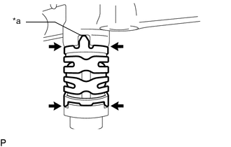
Install the nozzle holder clamp to each fuel injector assembly.
-
*a Protrusion 
No Gap Apply gasoline to the O-ring. Install each fuel injector assembly by aligning the protrusion of the nozzle holder clamp with the notch of the fuel delivery pipe sub-assembly and No. 2 fuel delivery pipe sub-assembly.
Note
-
Make sure that there is no gap between the fuel delivery pipe sub-assembly, No. 2 fuel delivery pipe sub-assembly and nozzle holder clamp.
-
Check that there is no foreign matter or damage on the fuel injector assembly installation holes of the fuel delivery pipe sub-assembly and No. 2 fuel delivery pipe sub-assembly.
-
Insert each fuel injector assembly straight into the fuel delivery pipe sub-assembly and No. 2 fuel delivery pipe sub-assembly without tilting it.
-
*a Insulator The fuel injector assembly connectors can be differentiated by the color of the insulators, which are either black, brown, green or yellow. Install the fuel injector assemblies so that the insulators are the same color for a given bank.
-
-
-
INSTALL FUEL DELIVERY PIPE SUB-ASSEMBLY
-
Install 3 new injector vibration insulators to the cylinder head sub-assembly.
-
Connect the 3 fuel injector assembly connectors.
-
Apply lubricant to the fuel injector assembly installation holes of the cylinder head sub-assembly.
-
*a Protruding enough to install nut Temporarily install the fuel delivery pipe sub-assembly so that the stud bolts protrude enough to install the nuts.
Note
-
If a fuel injector assembly is dropped or the tip of a fuel injector assembly is struck, replace it with a new one.
-
Check that there is no foreign matter or damage on the fuel injector assembly installation holes of the cylinder head sub-assembly.
-
When installing the fuel delivery pipe sub-assembly, push it in evenly without tilting it.
-
-
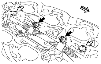
Nut 
Bolt 
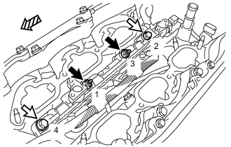
Front Side Install the fuel delivery pipe sub-assembly by uniformly tightening the 2 bolts and 2 nuts in the order shown in the illustration.
- Torque:
- 26 N*m { 265 kgf*cm, 19 ft.*lbf }
-
Engage the 2 clamps to connect the No. 6 engine wire.
-
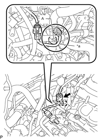
*a Wire Harness Engage the clamp to connect the wire harness.
Note
-
Make sure the wire harness of the fuel pressure sensor passes under the area (A) as shown in the illustration.
-
Do not pull the wire harness of the fuel pressure sensor excessively.
-
-
Connect the fuel pressure sensor connector.
-
-
INSTALL NO. 2 FUEL DELIVERY PIPE SUB-ASSEMBLY
-
Install 3 new injector vibration insulators to the cylinder head sub-assembly.
-
Connect the 3 fuel injector assembly connectors.
-
Apply lubricant to the fuel injector assembly installation holes of the cylinder head sub-assembly.
-
*a Protruding enough to install nut Temporarily install the No. 2 fuel delivery pipe sub-assembly so that the stud bolts protrude enough to install the nuts.
Note
-
If a fuel injector assembly is dropped or the tip of a fuel injector assembly is struck, replace it with a new one.
-
Check that there is no foreign matter or damage on the fuel injector assembly installation holes of the cylinder head sub-assembly.
-
When installing the No. 2 fuel delivery pipe sub-assembly, push it in evenly without tilting it.
-
-
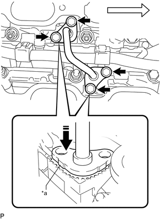
Nut Bolt Front Side Install the No. 2 fuel delivery pipe sub-assembly by uniformly tightening the 2 bolts and 2 nuts in the order shown in the illustration.
- Torque:
- 26 N*m { 265 kgf*cm, 19 ft.*lbf }
-
Engage the 3 clamps to connect the No. 7 engine wire.
-
-
INSTALL NO. 3 FUEL PIPE SUB-ASSEMBLY
-
Install a new O-ring, new No. 1 back-up ring, new No. 2 back-up ring, new No. 3 back-up ring and new E-ring to each end of the No. 3 fuel pipe sub-assembly as shown in the illustration.
*1 No. 1 Back-up Ring *2 No. 2 Back-up Ring *3 No. 3 Back-up Ring *4 O-ring *5 E-ring - - *a Alignment Opening *b Overlapped *c Stretched *d Correct *e Incorrect - - Note
-
Check that there is no foreign matter or damage on the O-ring grooves of the No. 3 fuel pipe sub-assembly.
-
Check that the No. 1 back-up ring and No. 2 back-up ring are installed in the correct orientation.
-
Make sure that the No. 1 back-up ring, No. 2 back-up ring, No. 3 back-up ring and O-ring are installed in the correct order.
-
Check that the alignment openings of the No. 1 back-up ring, No. 2 back-up ring and No. 3 back-up ring are not overlapped or stretched as shown in the illustration.
-
After installing the O-rings, check that they are not contaminated with foreign matter and are not damaged.
-
Check that the ends of the No. 3 fuel pipe sub-assembly are not contaminated with foreign matter and are not damaged.
-
-
*a No Gap Front Side Apply engine oil to the installation hole of the fuel delivery pipe sub-assembly and No. 2 fuel delivery pipe sub-assembly.
-
Press the No. 3 fuel pipe sub-assembly by hand until there is no gap between the No. 3 fuel pipe sub-assembly and either fuel delivery pipe sub-assembly or No. 2 fuel delivery pipe sub-assembly, then install the No. 3 fuel pipe sub-assembly with the 4 bolts.
- Torque:
- 10 N*m { 102 kgf*cm, 7 ft.*lbf }
Note
Do not install the No. 3 fuel pipe sub-assembly at an angle.
-
-
INSTALL FUEL PUMP ASSEMBLY
-
PERFORM INITIALIZATION (w/ Canister Pump Module)
-
Perform "Inspection After Repair" after replacing a fuel injector assembly.
-