ENGINE UNIT REASSEMBLY

PROCEDURE
-
INSTALL CAMSHAFT BEARING CAP SETTING RING PIN
Tech Tips
It is not necessary to remove the camshaft bearing cap setting ring pins unless they are being replaced.
-
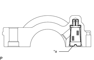
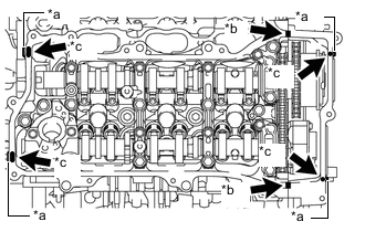
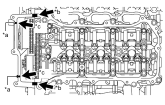
Using a plastic hammer, tap in 20 new camshaft bearing cap setting ring pins into the camshaft housing sub-assembly and camshaft housing sub-assembly LH.
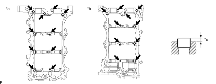
*a for Bank 2 *b for Bank 1 *c Protrusion Height - - Standard Protrusion Height 2.7 to 3.3 mm (0.106 to 0.130 in.)
-
-
INSTALL STRAIGHT PIN
Tech Tips
It is not necessary to remove the straight pin unless it is being replaced.
-
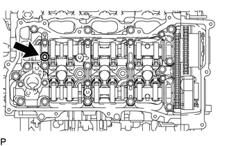
Using a plastic hammer, tap in 2 new straight pins to the camshaft housing sub-assembly and camshaft housing sub-assembly LH.
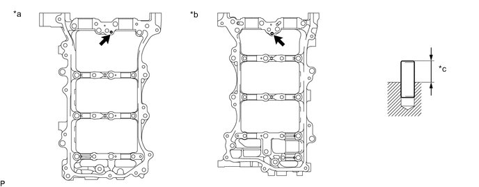
*a for Bank 2 *b for Bank 1 *c Protrusion Height - - Standard Protrusion Height 7.7 to 8.3 mm (0.303 to 0.327 in.)
-
-
INSTALL CYLINDER BLOCK WATER JACKET SPACER
-
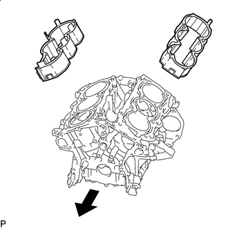

Front of Engine Install the 2 cylinder block water jacket spacers as shown in the illustration.
-
-
INSTALL ENGINE REAR OIL SEAL
-
Place the engine rear oil seal retainer on wooden blocks.
-
Apply MP grease to the lip of a new engine rear oil seal.
-
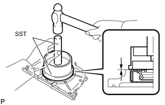
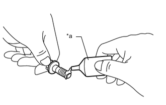
Using SST and a hammer, tap in the engine rear oil seal.
- SST
- 09223-15030
- 09950-70010 ( 09951-07100 )
Oil Seal Protrusion Height -0.5 to 0.5 mm (-0.0197 to 0.0197 in.) Note
-
Keep the lip free of foreign matter.
-
Do not tap in the engine rear oil seal at an angle.
-
-
INSTALL ENGINE REAR OIL SEAL RETAINER
-
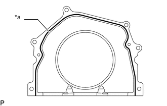
*a Seal Packing Apply seal packing in a continuous line as shown in the illustration.
Seal Packing Toyota Genuine Seal Packing Black, Three Bond 1207B or equivalent Seal Packing Diameter 2.0 to 3.0 mm (0.0787 to 0.118 in.) Note
-
Remove any oil from the contact surface.
-
Install the engine rear oil seal retainer within 3 minutes of applying seal packing.
-
Do not start the engine for at least 2 hours after installation.
-
-
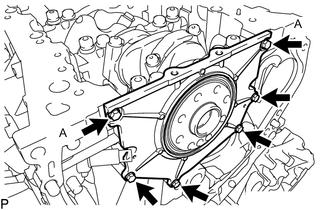
Install the engine rear oil seal retainer with the 6 new bolts.
- Torque:
- 10 N*m { 102 kgf*cm, 7 ft.*lbf }
Adhesive Toyota Genuine Adhesive 1324, Three Bond 1324 or equivalent Note
-
Be sure to apply adhesive to the bolts (A) before installing them.
-
Install the bolt within 3 minutes after applying adhesive.
-
-
INSTALL NO. 1 WATER OUTLET PIPE
-
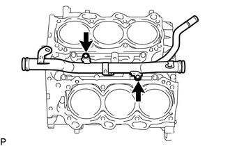
Install the No. 1 water outlet pipe with the 2 bolts.
- Torque:
- 10 N*m { 102 kgf*cm, 7 ft.*lbf }
-
-
INSTALL KNOCK CONTROL SENSOR
-
INSTALL NO. 5 ENGINE WIRE
-
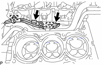
Install the No. 5 engine wire with the 2 clamps.
-
Engage the 2 connectors.
-
-
INSTALL CYLINDER HEAD GASKET
-
INSTALL CYLINDER HEAD SUB-ASSEMBLY
-
INSTALL NO. 2 CYLINDER HEAD GASKET
-
INSTALL CYLINDER HEAD LH
-
INSTALL VALVE STEM CAP
-
INSTALL VALVE LASH ADJUSTER ASSEMBLY
-
INSTALL NO. 1 VALVE ROCKER ARM SUB-ASSEMBLY
-
INSTALL OIL CONTROL VALVE FILTER (for Bank 1)
-
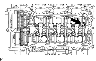
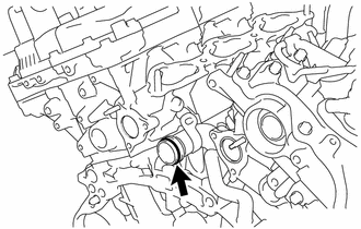
*a Camshaft Installation Surface Install the 2 oil control valve filters to the 2 camshaft bearing caps.
Note
Make sure the oil control valve filter does not protrude past the camshaft installation surface shown in the illustration.
-
-
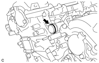
INSTALL OIL CONTROL VALVE FILTER (for Bank 2)
-
Install the 2 oil control valve filters to the 2 camshaft bearing caps.
Note
Make sure the oil control valve filter does not protrude past the camshaft installation surface shown in the illustration.
-
-
INSTALL NO. 3 CAMSHAFT SUB-ASSEMBLY
-
INSTALL NO. 4 CAMSHAFT SUB-ASSEMBLY
-
INSTALL CAMSHAFT BEARING CAP (for Bank 2)
-
INSTALL NO. 3 CHAIN TENSIONER ASSEMBLY
-
SET CAMSHAFT TIMING GEAR ASSEMBLY, CAMSHAFT TIMING EXHAUST GEAR ASSEMBLY AND NO. 2 CHAIN SUB-ASSEMBLY (for Bank 2)
-
TEMPORARILY INSTALL CAMSHAFT TIMING GEAR BOLT (for Intake Side of Bank 2)
-
TEMPORARILY INSTALL CAMSHAFT TIMING GEAR BOLT (for Exhaust Side of Bank 2)
-
INSTALL CAMSHAFT HOUSING SUB-ASSEMBLY LH
-
TIGHTEN CAMSHAFT TIMING GEAR BOLT (for Intake Side of Bank 2)
-
TIGHTEN CAMSHAFT TIMING GEAR BOLT (for Exhaust Side of Bank 2)
-
INSTALL CAMSHAFT
-
INSTALL NO. 2 CAMSHAFT
-
INSTALL FUEL PUMP LIFTER HOUSING
-
INSTALL CAMSHAFT BEARING CAP (for Bank 1)
-
INSTALL NO. 2 CHAIN TENSIONER ASSEMBLY
-
SET CAMSHAFT TIMING GEAR ASSEMBLY, CAMSHAFT TIMING EXHAUST GEAR ASSEMBLY AND NO. 2 CHAIN SUB-ASSEMBLY (for Bank 1)
-
TEMPORARILY INSTALL CAMSHAFT TIMING GEAR BOLT (for Intake Side of Bank 1)
-
TEMPORARILY INSTALL CAMSHAFT TIMING GEAR BOLT (for Exhaust Side of Bank 1)
-
INSTALL CAMSHAFT HOUSING SUB-ASSEMBLY RH
-
TIGHTEN CAMSHAFT TIMING GEAR BOLT (for Intake Side of Bank 1)
-
TIGHTEN CAMSHAFT TIMING GEAR BOLT (for Exhaust Side of Bank 1)
-
INSTALL NO. 1 CHAIN VIBRATION DAMPER
-
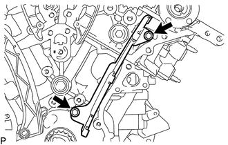
Install the No. 1 chain vibration damper with the 2 bolts.
- Torque:
- 22.5 N*m { 229 kgf*cm, 17 ft.*lbf }
-
-
INSTALL NO. 2 CHAIN VIBRATION DAMPER
-
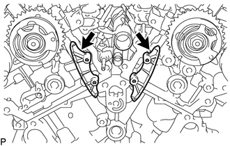
Install the 2 No. 2 chain vibration dampers.
-
-
INSTALL CRANKSHAFT TIMING GEAR OR SPROCKET
-
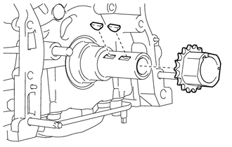
Install the 2 crankshaft timing gear set keys and crankshaft timing gear or sprocket to the crankshaft.
-
-
INSTALL IDLE SPROCKET ASSEMBLY
-
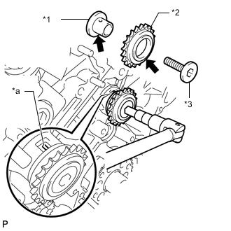
*1 No. 1 Idle Gear Shaft *2 Idle Sprocket Assembly *3 No. 2 Idle Gear Shaft *a Knock Pin Light coat of engine oil Apply a light coat of engine oil to the rotating surface of the No. 1 idle gear shaft.
-
Temporarily install the No. 1 idle gear shaft and idle sprocket assembly with the No. 2 idle gear shaft while aligning the knock pin of the No. 1 idle gear with the pin hole of the cylinder block sub-assembly.
Note
Make sure to install the No. 1 idle gear shaft installation in the correct direction.
Tech Tips
Check that there is no foreign matter on the No. 1 idle gear shaft or No. 2 idle gear shaft.
-
Using a 10 mm hexagon socket wrench, tighten the No. 2 idle gear shaft.
- Torque:
- 60 N*m { 612 kgf*cm, 44 ft.*lbf }
Tech Tips
After installing the idle sprocket assembly, check that the idle sprocket assembly turns smoothly.
-
-
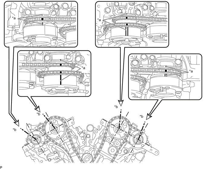
INSTALL CHAIN SUB-ASSEMBLY
-
Check that the camshaft timing gear position on the bank 2 and the timing marks on the bank 1 and crankshaft are positioned as shown in the illustration.
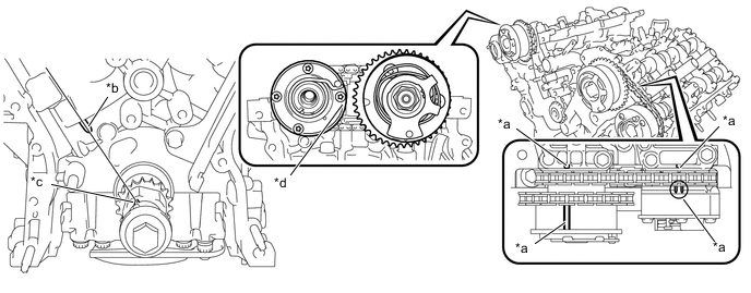
*a Timing Mark *b Center Line *c Crankshaft Timing Gear Set Key *d Flat Surface Tech Tips
The flat surface on the camshaft timing exhaust gear assembly must be positioned as shown in the illustration.
-
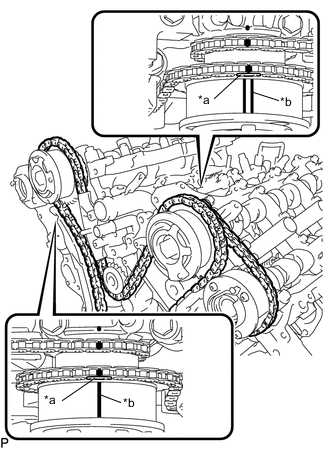
*a Mark Plate (Yellow) *b Timing Mark Align the mark plates and timing marks as shown in the illustration and install the chain sub-assembly.
Tech Tips
The camshaft mark plates are yellow.
-
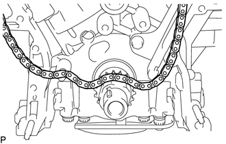
Temporarily place the chain sub-assembly on the crankshaft as shown in the illustration.
-
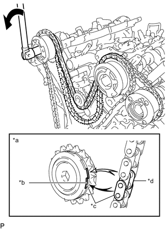
*a When the idle sprocket assembly is reused *b Mark *c Align *d Chain Plate Turn Turn the camshaft timing gear assembly on bank 1 counterclockwise to tighten the chain sub-assembly between the banks.
Note
When reusing the idle sprocket assembly, align the chain plate with the mark where the mark plate had been in order to tighten the chain sub-assembly between the banks.
-
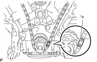
*a Mark Plate (Pink) *b Timing Mark Align the mark plate and timing marks as shown in the illustration and install the chain sub-assembly around the crankshaft timing gear or sprocket.
Tech Tips
The crankshaft mark plate is pink.
-
Temporarily tighten the crankshaft pulley set bolt to the crankshaft.
-
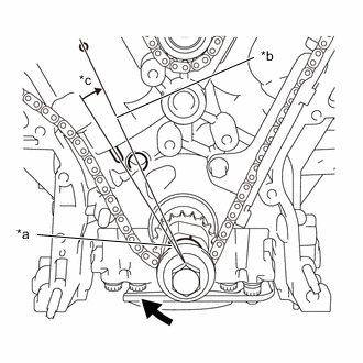
*a Timing Gear Set Key *b Center Line *c 10° Turn the crankshaft clockwise to set it to the center line of the block bore (for Bank 1) (TDC /compression).
-
-
INSTALL CHAIN TENSIONER SLIPPER
-
Install the chain tensioner slipper.
-
-
INSTALL NO. 1 CHAIN TENSIONER ASSEMBLY
-
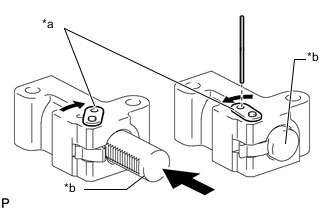
*a Stopper Plate *b Plunger Turn the stopper plate clockwise to release the lock, and push the plunger deep into the No. 1 chain tensioner assembly.
-
Turn the stopper plate counterclockwise to set the lock, and insert a 1.0 mm (0.0394 in.) diameter pin into the hole of the stopper plate.
-
Install the No. 1 chain tensioner assembly with the 2 bolts.
- Torque:
- 10 N*m { 102 kgf*cm, 7 ft.*lbf }
-
Remove the 1.0 mm (0.0394 in.) diameter pin from the No. 1 chain tensioner assembly.
-
-
INSPECT VALVE TIMING
-
Check the camshaft timing marks.
Note
-
Check each timing mark from a viewpoint directly in line with the center of the camshaft and the timing mark on each camshaft timing gear assembly and each camshaft timing exhaust gear assembly.
-
If the timing marks are checked from any other viewpoint, the valve timing may appear misaligned.
-
-
Check that each camshaft timing mark is positioned as shown in the illustration.
*a Timing Mark *b Viewpoint Tech Tips
For the camshaft or No. 3 camshaft sub-assembly:
Be sure to check the mark (A) at the point where the marks (B), (C) and (D) are positioned in line. If the marks are checked from any other viewpoint, they cannot be checked correctly.

-
If the valve timing is misaligned, reinstall the chain sub-assembly.
-
Remove the crankshaft pulley set bolt.
-
-
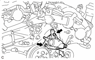
INSTALL ENGINE WATER PUMP ASSEMBLY
-
Install a new water pump gasket.
-
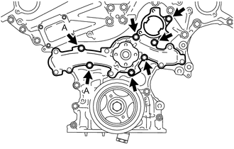
Install the engine water pump assembly with the 7 bolts.
Note
-
Be sure to apply adhesive to the 2 bolts labeled A before reusing them, or replace them with new ones if necessary.
-
Install the bolt within 3 minutes after applying adhesive.
Adhesive Toyota Genuine Adhesive 1344, Three Bond 1344 or equivalent -
-
-
INSTALL TIMING CHAIN COVER ASSEMBLY
-
INSTALL TIMING CHAIN COVER PLATE
-
INSTALL TIMING CHAIN CASE OIL SEAL
-
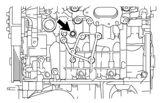
INSTALL NO. 1 OIL PAN BAFFLE PLATE
-
Install the No. 1 oil pan baffle plate with the 8 bolts.
- Torque:
- 10 N*m { 102 kgf*cm, 7 ft.*lbf }
Tech Tips
Temporarily install the 8 bolts. Tighten the 2 bolts (A) shown in the illustration before tightening the other bolts.
-
-
INSTALL OIL STRAINER SUB-ASSEMBLY
-
Install a new gasket and the oil strainer sub-assembly with the 3 nuts.
- Torque:
- 10 N*m { 102 kgf*cm, 7 ft.*lbf }
-
-
INSTALL OIL PAN SUB-ASSEMBLY
-
Remove any remaining seal packing material and be careful not to drop any oil on the contact surfaces of the cylinder block sub-assembly and oil pan sub-assembly.
-
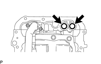
Install 2 new O-rings to the timing chain cover assembly.
-
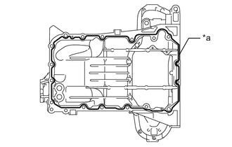
*a Seal Packing Apply seal packing in a continuous line as shown in the illustration.
Seal Packing Toyota Genuine Seal Packing Black, Three Bond 1207B or equivalent Seal Packing Diameter 3.0 to 4.0 mm (0.118 to 0.157 in.) Note
-
Remove any oil from the contact surface.
-
Install the oil pan sub-assembly within 3 minutes of applying seal packing.
-
Do not start the engine for at least 2 hours after installation.
-
-
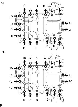
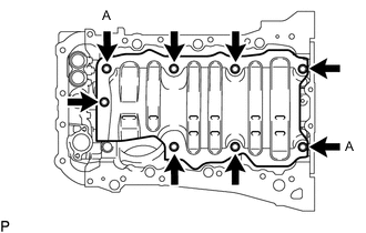
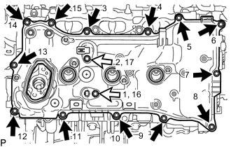
*a Torque *b Bolt and Nut Tightening Order Bolt 
Nut Install the oil pan sub-assembly with the 16 bolts and 2 nuts.
- Torque:
- Bolt (A)
- 10 N*m { 102 kgf*cm, 7 ft.*lbf }
- Bolt (B), (C), (D) and Nut
- 21 N*m { 214 kgf*cm, 15 ft.*lbf }
Bolt Length Item Length Bolt (A) 16 mm (0.630 in.) Bolt (B) 25 mm (0.984 in.) Bolt (C) 45 mm (1.77 in.) Bolt (D) 70 mm (2.76 in.) -

Wipe off the Seal Packing Wipe off any excess seal packing with a clean piece of cloth.
Note
Do not allow seal packing to contact the No. 1 crankshaft position sensor plate.
-
-
INSTALL OIL LEVEL SENSOR BRACKET
-
INSTALL ENGINE OIL LEVEL SENSOR
-
INSTALL NO. 2 OIL PAN SUB-ASSEMBLY
-
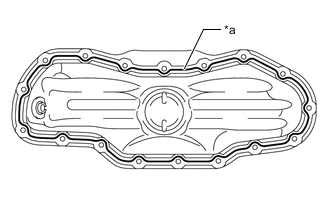
*a Seal Packing Apply seal packing in a continuous line as shown in the illustration.
Seal Packing Toyota Genuine Seal Packing Black, Three Bond 1207B or equivalent Seal Packing Diameter 3.0 to 4.0 mm (0.118 to 0.157 in.) Note
-
Remove any oil from the contact surface.
-
Install the No. 2 oil pan sub-assembly within 3 minutes of applying seal packing.
-
Do not start the engine for at least 2 hours after installation.
-
-
Bolt Nut Install the No. 2 oil pan sub-assembly with the 15 bolts and 2 nuts in the order shown in the illustration.
- Torque:
- 10 N*m { 102 kgf*cm, 7 ft.*lbf }
-
-
INSTALL OIL PAN DRAIN PLUG
-
Install a new gasket and the oil pan drain plug.
- Torque:
- 40 N*m { 408 kgf*cm, 30 ft.*lbf }
-
-
INSTALL SPARK PLUG TUBE GASKET
-
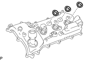
Install 6 new spark plug tube gaskets to the cylinder head cover sub-assembly and cylinder head cover sub-assembly LH.
-
-
INSTALL CYLINDER HEAD COVER SUB-ASSEMBLY
-
Remove any remaining seal packing material and be careful not to drop any oil on the contact surfaces of the camshaft housing sub-assembly RH, timing chain cover assembly and cylinder head cover sub-assembly.
-
*a Mark *b Seal Packing (Diameter 2.0 to 3.0 mm (0.0787 to 0.118 in.)) *c Seal Packing (Diameter 5.0 to 7.0 mm (0.197 to 0.276 in.)) Seal Packing Apply seal packing as shown in the illustration.
Seal Packing Toyota Genuine Seal Packing Black, Three Bond 1207B or equivalent Note
-
Remove any oil from the contact surface.
-
Install the cylinder head cover sub-assembly within 3 minutes and tighten the bolts within 15 minutes of applying seal packing.
-
Do not start the engine for at least 2 hours after installation.
-
-
Install a new camshaft bearing cap oil hole gasket RH to the camshaft housing sub-assembly RH.
-
Install 2 new gaskets and a cylinder head cover gasket.
-
Apply a light coat of engine oil to the 2 new O-ring of the 2 VVT sensors (for intake side of bank 1 and for exhaust side of bank 1).
Note
If reusing the 2 VVT sensors (for Exhaust Side of Bank 1 and for Intake Side of Bank 1), be sure to inspect them before installation.
-
Clean the 2 bolts and 2 bolt holes of the VVT sensors (for Exhaust Side of Bank 1 and for Intake Side of Bank 1).
-
*a Adhesive Apply adhesive to 2 or 3 threads at the end of the 2 bolts of the VVT sensors (for Exhaust Side of Bank 1 and for Intake Side of Bank 1).
Adhesive Toyota Genuine Adhesive 1324, Three Bond 1324 or equivalent -
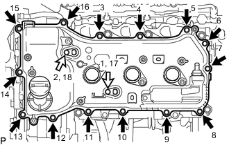
Bolt (A) Bolt (B) Install the cylinder head cover sub-assembly with the 15 bolts and 2 VVT sensors (for Exhaust Side of Bank 1 and for Intake Side of Bank 1) in the order shown in the illustration.
- Torque:
- 10 N*m { 102 kgf*cm, 7 ft.*lbf }
Note
-
If a VVT sensor (for Exhaust Side of Bank 1 or for Intake Side of Bank 1) has been struck or dropped, replace it.
-
Make sure that the 2 O-rings are not cracked or moved out of place when installing the 2 VVT sensors (for Exhaust Side of Bank 1 and for Intake Side of Bank 1).
Tech Tips
After tightening all bolts, check the tightening torque of the bolts (1) and (17). Retighten them if necessary.
Bolt Length Item Length Bolt (A) 25 mm (0.984 in.) Bolt (B) 23.5 mm (0.925 in.)
-
-
INSTALL CYLINDER HEAD COVER SUB-ASSEMBLY LH
-
Remove any remaining seal packing material and be careful not to drop any oil on the contact surfaces of the camshaft housing sub-assembly LH, timing chain cover assembly and cylinder head cover sub-assembly LH.
-
*a Mark *b Seal Packing (Diameter 2.0 to 3.0 mm (0.0787 to 0.118 in.)) *c Seal Packing (Diameter 5.0 to 7.0 mm (0.197 to 0.276 in.)) Seal Packing Apply seal packing as shown in the illustration.
Seal Packing Toyota Genuine Seal Packing Black, Three Bond 1207B or equivalent Note
-
Remove any oil from the contact surface.
-
Install the cylinder head cover sub-assembly LH within 3 minutes and tighten the bolts within 15 minutes of applying seal packing.
-
Do not start the engine for at least 2 hours after installation.
-
-
Install a new camshaft bearing cap oil hole gasket LH to the camshaft housing sub-assembly LH.
-
Install 2 new gaskets and a cylinder head cover gasket.
-
Apply a light coat of engine oil to the 2 new O-rings of the 2 VVT sensors (for Exhaust Side of Bank 2 and for Intake Side of Bank 2).
Note
If reusing the 2 VVT sensors (for Exhaust Side of Bank 2 and for Intake Side of Bank 2), be sure to inspect them before installation.
-
Clean the 2 bolts and 2 bolt holes of the VVT sensors (for Exhaust Side of Bank 2 and for Intake Side of Bank 2).
-
*a Adhesive Apply adhesive to 2 or 3 threads at the end of the 2 bolts of the VVT sensors (for Exhaust Side of Bank 2 and for Intake Side of Bank 2).
Adhesive Toyota Genuine Adhesive 1324, Three Bond 1324 or equivalent -
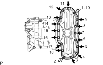
Bolt (A) Bolt (B) Install the cylinder head cover sub-assembly LH with the 16 bolts and 2 VVT sensors (for Exhaust Side of Bank 2 and for Intake Side of Bank 2) in the order shown in the illustration.
- Torque:
- 10 N*m { 102 kgf*cm, 7 ft.*lbf }
Note
-
If a VVT sensor (for Exhaust Side of Bank 2 or for Intake Side of Bank 2) has been struck or dropped, replace it.
-
Make sure that the 2 O-rings are not cracked or moved out of place when installing the 2 VVT sensors (for Exhaust Side of Bank 2 and for Intake Side of Bank 2).
Tech Tips
After tightening all bolts, check the tightening torque of the bolts (1) and (18). Retighten them if necessary.
Bolt Length Item Length Bolt (A) 25 mm (0.984 in.) Bolt (B) 23.5 mm (0.925 in.)
-
-
INSTALL VACUUM PUMP ASSEMBLY
-
INSTALL REAR WATER BY-PASS JOINT
-
Install a new O-ring to the No. 1 water outlet pipe.
Tech Tips
Apply water to the O-ring.
-
Install 2 new water by-pass joint gaskets to the rear water by-pass joint.
-
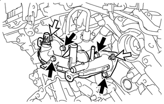
Bolt Nut Install the rear water by-pass joint with the 4 bolts and 2 nuts.
- Torque:
- 10 N*m { 102 kgf*cm, 7 ft.*lbf }
Note
Be careful that the O-ring does not get caught between the parts.
-
-
INSTALL CAMSHAFT TIMING OIL CONTROL SOLENOID ASSEMBLY (for Intake Side of Bank 1)
-
INSTALL CAMSHAFT TIMING OIL CONTROL SOLENOID ASSEMBLY (for Exhaust Side of Bank 1)
-
INSTALL CAMSHAFT TIMING OIL CONTROL SOLENOID ASSEMBLY (for Intake Side of Bank 2)
-
INSTALL CAMSHAFT TIMING OIL CONTROL SOLENOID ASSEMBLY (for Exhaust Side of Bank 2)
-
INSTALL WATER INLET WITH THERMOSTAT SUB-ASSEMBLY
-
Bolt Nut Install a new gasket and the water inlet with thermostat sub-assembly with the 2 bolts and nut.
- Torque:
- 10 N*m { 102 kgf*cm, 7 ft.*lbf }
-
-
INSTALL WATER OUTLET SUB-ASSEMBLY
-
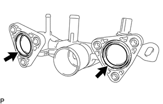
Install a new O-ring to the No. 1 water outlet pipe.
-

Install the water outlet sub-assembly with the 2 bolts.
- Torque:
- 21 N*m { 214 kgf*cm, 15 ft.*lbf }
Note
Be careful that the O-ring does not get caught between the parts.
-
-
INSTALL CRANKSHAFT PULLEY
-
INSTALL OIL COOLER ASSEMBLY (w/ Oil Cooler)
-
INSTALL OIL FILTER BRACKET SUB-ASSEMBLY
-
INSTALL OIL FILTER CAP ASSEMBLY
-
INSTALL CYLINDER BLOCK WATER DRAIN COCK PLUG
-
Apply adhesive around the cylinder block water drain cock plug.
Adhesive Toyota Genuine Adhesive 1344, Three Bond 1344 or equivalent -
Install the cylinder block water drain cock plug.
- Torque:
- 25 N*m { 255 kgf*cm, 18 ft.*lbf }
Note
Install the cylinder block water drain cock plug within 3 minutes after applying adhesive.
-
-
INSTALL CYLINDER BLOCK WATER DRAIN COCK SUB-ASSEMBLY
-
Apply adhesive around the cylinder block water drain cock sub-assembly.
Adhesive Toyota Genuine Adhesive 1344, Three Bond 1344 or equivalent -
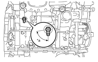
*a 80° Install the cylinder block water drain cock sub-assembly as shown in the illustration.
- Torque:
- 25 N*m { 255 kgf*cm, 18 ft.*lbf }
Note
-
Install the cylinder block water drain cock sub-assembly within 3 minutes after applying adhesive.
-
Do not rotate the cylinder block water drain cock sub-assembly more than 1 revolution (360°) after tightening the drain cock to the specified torque.
-
Do not loosen the cylinder block water drain cock sub-assembly after setting it correctly.
-
Do not add engine coolant for at least 1 hour after installing the cylinder block water drain cock sub-assembly.
-
Install the water drain cock plug to the cylinder block water drain cock sub-assembly.
- Torque:
- 12.7 N*m { 130 kgf*cm, 9 ft.*lbf }
-
-
INSTALL CRANKSHAFT POSITION SENSOR
-
INSTALL PCV VALVE (VENTILATION VALVE SUB-ASSEMBLY)
-
INSTALL VENTILATION HOSE ASSEMBLY
-
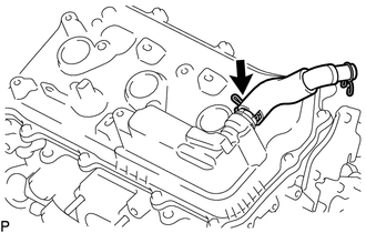
Install the ventilation hose assembly to the cylinder head cover sub-assembly LH with the hose clamp.
-
-
INSTALL NO. 1 FUEL TUBE SUB-ASSEMBLY
-
INSTALL NO. 1 ENGINE COVER SUB-ASSEMBLY
-
for Bank 1:
Install the No. 1 engine cover to the cylinder head cover sub-assembly with the 2 clips.
-
for Bank 2:
Install the No. 1 engine cover to the No. 1 fuel tube sub-assembly with the clip.
-
-
INSTALL SPARK PLUG