CAMSHAFT REMOVAL
PROCEDURE
-
DRAIN ENGINE COOLANT
-
PRECAUTION
Note
After turning the engine switch off, waiting time may be required before disconnecting the cable from the battery terminal. Therefore, make sure to read the disconnecting the cable from the battery terminal notice before proceeding with work.
-
DISCONNECT CABLE FROM NEGATIVE BATTERY TERMINAL
-
REMOVE BATTERY
-
REMOVE NO. 1 BATTERY TRAY SUPPORT
-
REMOVE FUEL PUMP ASSEMBLY (for High Pressure)
-
SEPARATE WIRE HARNESS
-
Remove the bolt, 4 nuts, 5 clamps and 2 connectors and separate the wire harness.

Bolt 
Nut 
connector - -
-
-
DISCONNECT INLET HEATER WATER HOSE A
-
DISCONNECT OUTLET HEATER WATER HOSE A
-
REMOVE NO. 2 WATER BY-PASS PIPE
-
DISCONNECT UNION TO CONNECTOR TUBE HOSE (for RHD)
-
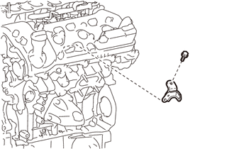
REMOVE VACUUM PUMP ASSEMBLY
-
REMOVE WIRE HARNESS CLAMP BRACKET
-
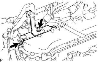
Disengage the wire harness clamp from the wire harness clamp bracket.
-
Remove the 2 bolts and the wire harness clamp bracket from cylinder head cover sub-assembly LH.
-
Remove the bolt and the wire harness clamp bracket from the cylinder head cover sub-assembly LH.
-
-
REMOVE NO. 1 RADIATOR HOSE
-
REMOVE NO. 2 RADIATOR HOSE SUB-ASSEMBLY
-
REMOVE WATER OUTLET SUB-ASSEMBLY
-
REMOVE NO. 1 WATER BY-PASS PIPE (w/ Oil Cooler)
-
REMOVE IGNITION COIL ASSEMBLY
-
REMOVE NO. 2 ENGINE OIL LEVEL DIPSTICK GUIDE
-
REMOVE CAMSHAFT TIMING OIL CONTROL SOLENOID ASSEMBLY (for Intake Side of Bank 1)
-
REMOVE CAMSHAFT TIMING OIL CONTROL SOLENOID ASSEMBLY (for Exhaust Side of Bank 1)
-
REMOVE CAMSHAFT TIMING OIL CONTROL SOLENOID ASSEMBLY (for Intake Side of Bank 2)
-
REMOVE CAMSHAFT TIMING OIL CONTROL SOLENOID ASSEMBLY (for Exhaust Side of Bank 2)
-
REMOVE NO. 1 ENGINE COVER SUB-ASSEMBLY
-
REMOVE CYLINDER HEAD COVER SUB-ASSEMBLY LH
-
REMOVE CYLINDER HEAD COVER SUB-ASSEMBLY
-
REMOVE SPARK PLUG TUBE GASKET
-
REMOVE TIMING CHAIN COVER PLATE
-
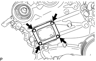
Remove the 4 bolts, timing chain cover plate and timing gear or chain cover gasket.
-
-
SET NO. 1 CYLINDER TO TDC/COMPRESSION
-
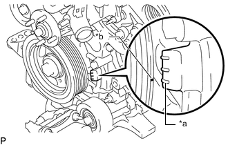
*a "0" Timing Mark *b Timing Mark (cutout) Turn the crankshaft clockwise to align the timing mark (cutout) on the crankshaft pulley with the "0" timing mark on the timing chain cover assembly.
-
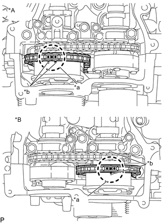
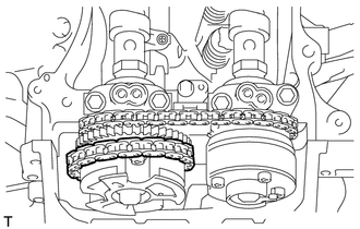
*A for Bank 2 *B for Bank 1 *a Paint Mark (yellow) *b Timing Mark Check that the timing marks of the camshaft timing gear assemblies are aligned with the timing marks of the camshaft bearing caps as shown in the illustration.
Tech Tips
If the marks are not aligned, turn the crankshaft again to align the marks.
-
Place paint marks on the timing marks and sprockets of each camshaft timing gear assembly and on the links of the chain sub-assembly.
Tech Tips
Be sure to place the paint marks on 2 links of the chain sub-assembly and on the sprockets of the camshaft timing gear assemblies at the locations of the timing marks of the camshaft timing gear assemblies.
-
-
REMOVE NO. 1 CHAIN TENSIONER ASSEMBLY
-
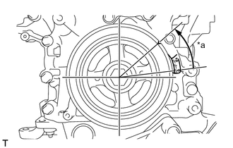
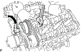
*a 30° Turn the crankshaft approximately 30° counterclockwise so that there is some slack in the chain sub-assembly.
Tech Tips
This prevents the valves and pistons from interfering with each other.
-
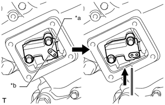
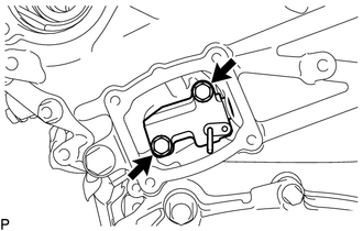
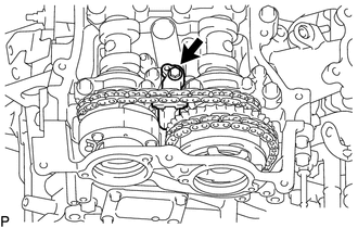
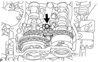
*a Lever Hole *b Tensioner Hole Align the hole in the lever of the No. 1 chain tensioner assembly with the hole in the tensioner body as shown in the illustration, and then insert a pin with a diameter of 1.0 mm (0.0394 in.) into the hole.
Note
Check that the pin is locked.
-
*a "0" Timing Mark *b Timing Mark (cutout) Turn the crankshaft clockwise to align the timing mark (cutout) on the crankshaft pulley with the "0" timing mark on the timing chain cover assembly.
-
Remove the 2 bolts and No. 1 chain tensioner assembly.
Note
Do not drop the No. 1 chain tensioner assembly or bolts into the timing chain cover assembly.
-
-
DISCONNECT CHAIN SUB-ASSEMBLY (for Bank 1)
-
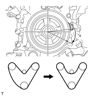
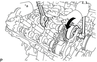
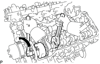
*a 30° Turn the crankshaft clockwise until it is in the position shown in the illustration so that there is some slack in the chain sub-assembly between the banks.
CAUTION:
As the camshafts may turn suddenly, do not touch the camshafts or camshaft timing gears.
Tech Tips
When turning the crankshaft, engine oil may spray out of the oil holes.
-
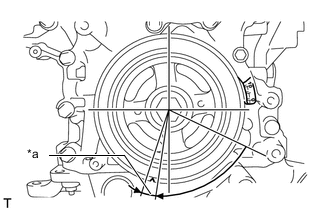
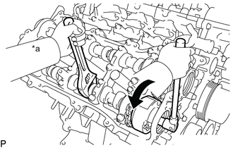
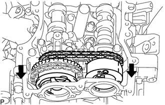
*a 5° to 10° Turn the crankshaft clockwise until it is in the position shown in the illustration so that the chain sub-assembly can be removed easily.
Tech Tips
When turning the crankshaft, engine oil may spray out of the oil holes.
-
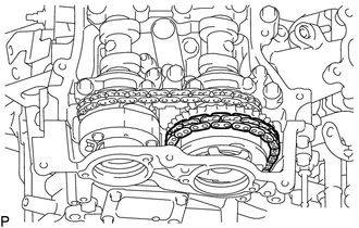
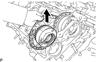
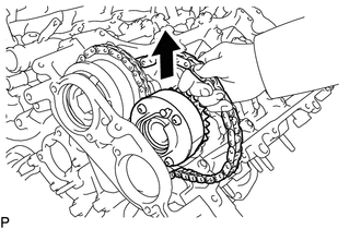
Remove the chain sub-assembly from the sprocket of the camshaft timing gear assembly and set it on the camshaft timing gear assembly.
CAUTION:
As the camshaft may turn suddenly and pinch your fingers when the chain sub-assembly is removed, pinch the chain sub-assembly and lift it upward to remove it from the sprocket.
-
-
REMOVE NO. 2 CHAIN TENSIONER ASSEMBLY
-
Remove the bolt of the No. 2 chain tensioner assembly.
-
-
REMOVE CAMSHAFT TIMING GEAR BOLT (for Intake Side of Bank 1)
-
*a Hold Turn Use a wrench to hold the hexagonal portion of the camshaft and remove the camshaft timing gear bolt from the camshaft timing gear assembly.
Note
Be careful not to damage the camshaft or camshaft housing sub-assembly with the wrench.
-
-
REMOVE CAMSHAFT TIMING GEAR BOLT (for Exhaust Side of Bank 1)
-
*a Hold Turn Hold the hexagonal portion of the No. 2 camshaft with a wrench and remove the camshaft timing gear bolt from the camshaft timing exhaust gear assembly RH.
Note
Be careful not to damage the No. 2 camshaft or camshaft housing sub-assembly with the wrench.
-
-
REMOVE CAMSHAFT BEARING CAP (for Bank 1)
-
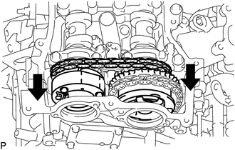
Slide the camshaft timing gear assembly and camshaft timing exhaust gear assembly RH as shown in the illustration.
-
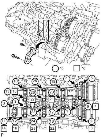
*a Replacement Bolt and Washer *b Part Removal *c Replacement Bolt and Washer Installation Remove the bolts and camshaft bearing caps in the order shown in the illustration. Immediately after removing a camshaft bearing cap, install replacement bolts and washers in the order shown in the illustration.
- Torque:
- 10 N*m { 102 kgf*cm, 7 ft.*lbf }
Note
-
Do not install the camshaft bearing caps when installing replacement bolts and washers.
-
Be sure to follow the numerical order when performing this procedure.
-
Do not allow replacement bolts or washers to contact the camshaft.
-
Do not drop replacement bolts or washers into the cylinder head sub-assembly.
Tech Tips
-
Arrange the removed parts so that they can be reinstalled in their original locations.
-
Part number for replacement bolts: 91551-F0850 (9 bolts)
-
Part number for replacement washers: 90201-12028 (18 washers)
-
-
REMOVE NO. 2 CAMSHAFT
-
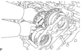
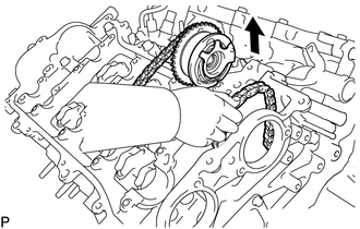
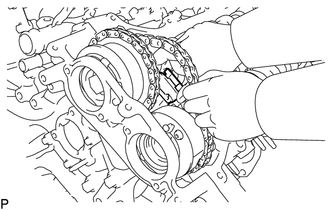
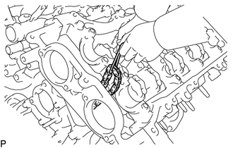
While lifting up the camshaft timing exhaust gear assembly RH, remove the No. 2 chain tensioner assembly.
-
Lift up the rear of the No. 2 camshaft so that it is at an angle.
-
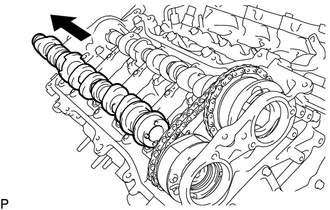
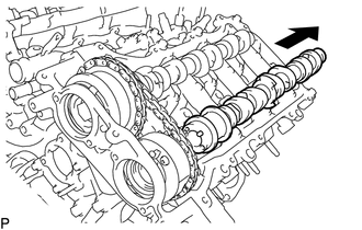
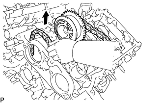
Pull the No. 2 camshaft as shown in the illustration to remove it from the camshaft timing exhaust gear assembly RH.
-
-
REMOVE CAMSHAFT
-
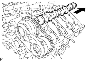
Lift up the rear of the camshaft so that it is at an angle.
-
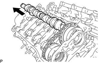
Pull the camshaft as shown in the illustration to remove it from the camshaft timing gear assembly.
-
-
REMOVE CAMSHAFT TIMING EXHAUST GEAR ASSEMBLY RH (for Bank 1)
-
Remove the camshaft timing exhaust gear assembly RH.
-
-
REMOVE CAMSHAFT TIMING GEAR ASSEMBLY (for Bank 1)
-
Remove the camshaft timing gear assembly and No. 2 chain sub-assembly.
Note
Do not drop the chain sub-assembly into the gap between the engine and timing chain cover assembly.
-
Suspend the chain sub-assembly with a string or equivalent.
-
-
DISCONNECT CHAIN SUB-ASSEMBLY (for Bank 2)
-

*a "0" Timing Mark *b Timing Mark (cutout) Turn the crankshaft counterclockwise to align the timing mark (cutout) on the crankshaft pulley with the "0" timing mark on the timing chain cover assembly.
-
Remove the chain sub-assembly from the sprocket of the camshaft timing gear assembly and set it on the camshaft timing gear assembly.
CAUTION:
As the camshaft may turn suddenly and pinch your fingers when the chain sub-assembly is removed, pinch the chain sub-assembly and lift it upward to remove it from the sprocket.
-
-
DISCONNECT NO. 3 CHAIN TENSIONER ASSEMBLY
-
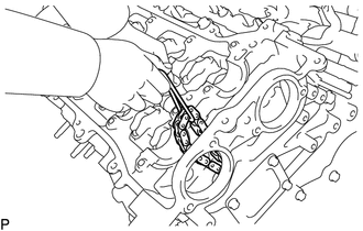
Remove the bolt to separate the No. 3 chain tensioner assembly from the camshaft housing sub-assembly LH.
-
-
REMOVE CAMSHAFT TIMING GEAR BOLT (for Intake Side of Bank 2)
-
*a Hold Turn Use a wrench to hold the hexagonal portion of the No. 3 camshaft sub-assembly and remove the camshaft timing gear bolt from the camshaft timing gear assembly.
Note
Be careful not to damage the No. 3 camshaft sub-assembly or cylinder head LH with the wrench.
-
-
REMOVE CAMSHAFT TIMING GEAR BOLT (for Exhaust Side of Bank 2)
-
*a Hold Turn Use a wrench to hold the hexagonal portion of the No. 4 camshaft sub-assembly and remove the camshaft timing gear bolt from the camshaft timing exhaust gear assembly LH.
Note
Be careful not to damage the No. 4 camshaft sub-assembly or cylinder head LH with the wrench.
-
-
REMOVE CAMSHAFT BEARING CAP (for Bank 2)
-
Slide the camshaft timing gear assembly and camshaft timing exhaust gear assembly LH as shown in the illustration.
-
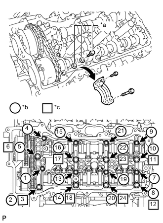
*a Replacement Bolt and Washer *b Part Removal *c Replacement Bolt and Washer Installation Remove the bolts and camshaft bearing caps in the order shown in the illustration. Immediately after removing a camshaft bearing cap, install replacement bolts and washers in the order shown in the illustration.
- Torque:
- 10 N*m { 102 kgf*cm, 7 ft.*lbf }
Note
-
Do not install the camshaft bearing caps when installing replacement bolts and washers.
-
Be sure to follow the numerical order when performing this procedure.
-
Do not allow replacement bolts or washers to contact the camshaft.
-
Do not drop replacement bolts or washers into the cylinder head LH.
Tech Tips
-
Arrange the removed parts so that they can be reinstalled in their original locations.
-
Part number for replacement bolts: 91551-F0850 (8 bolts)
-
Part number for replacement washers: 90201-12028 (16 washers)
-
-
REMOVE NO. 4 CAMSHAFT SUB-ASSEMBLY
-
While lifting up the camshaft timing exhaust gear assembly LH, remove the No. 3 chain tensioner assembly.
-
Lift up the rear of the No. 4 camshaft sub-assembly so that it is at an angle.
-
Pull the No. 4 camshaft sub-assembly toward the rear of the vehicle to remove it from the camshaft timing exhaust gear assembly LH.
-
-
REMOVE NO. 3 CAMSHAFT SUB-ASSEMBLY
-
Lift up the rear of the No. 3 camshaft sub-assembly so that it is at an angle.
-
Pull the No. 3 camshaft sub-assembly as shown in the illustration to remove it from the camshaft timing gear assembly.
-
-
REMOVE CAMSHAFT TIMING EXHAUST GEAR ASSEMBLY LH (for Bank 2)
-
Remove the camshaft timing exhaust gear assembly LH.
-
-
REMOVE CAMSHAFT TIMING GEAR ASSEMBLY (for Bank 2)
-
Remove the camshaft timing gear assembly and No. 2 chain sub-assembly.
Note
Do not drop the chain sub-assembly into the gap between the engine and timing chain cover assembly.
-
Suspend the chain sub-assembly with a string or equivalent.
-