CYLINDER HEAD REPLACEMENT

PROCEDURE
-
REPLACE INTAKE VALVE GUIDE BUSH
-
Heat the cylinder head to 80 to 100°C (176 to 212°F).
-
Place the cylinder head on wooden blocks.
CAUTION:
Be sure to wear protective gloves.
-
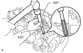
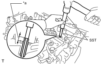
Using SST and a hammer, tap out the intake valve guide bushes.
- SST
- 09201-10000 ( 09201-01050 )
- 09950-70010 ( 09951-07100 )
-
Using a caliper gauge, measure the intake valve guide bush bore diameter of the cylinder head.
Standard Intake Valve Guide Bush Bore Diameter 10.285 to 10.306 mm (0.4049 to 0.4057 in.) Select a New Intake Valve Guide Bush (STD or O/S 0.05) Bush Size Specified Condition STD 10.285 to 10.306 mm
(0.4049 to 0.4057 in.)
O/S 0.05 10.335 to 10.356 mm
(0.4069 to 0.4077 in.)
Tech Tips
-
If the intake valve guide bush bore diameter is more than 10.306 mm (0.4057 in.), machine the bush bore to a dimension of 10.335 to 10.356 mm (0.4069 to 0.4077 in.) to install an O/S 0.05 intake valve guide bush.
-
If the intake valve guide bush bore diameter is more than 10.356 mm (0.4077 in.), replace the cylinder head.
-
-
Heat the cylinder head to 80 to 100°C (176 to 212°F).
-
Place the cylinder head on wooden blocks.
CAUTION:
Be sure to wear protective gloves.
-
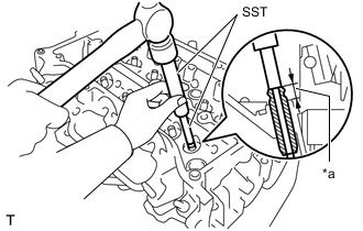
*a Protrusion Height Using SST, tap in new intake valve guide bushes to the specified protrusion height.
- SST
- 09201-10000 ( 09201-01050 )
- 09950-70010 ( 09951-07100 )
Standard Protrusion Height 9.10 to 9.90 mm (0.358 to 0.390 in.) -
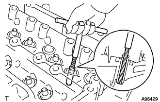
Using a sharp 5.5 mm reamer, ream the intake valve guide bushes to obtain the specified oil clearance.
Standard Oil Clearance 0.030 to 0.060 mm (0.00118 to 0.00236 in.)
-
-
REPLACE EXHAUST VALVE GUIDE BUSH
-
Heat the cylinder head to 80 to 100°C (176 to 212°F).
-
Place the cylinder head on wooden blocks.
CAUTION:
Be sure to wear protective gloves.
-
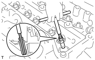
Using SST and a hammer, tap out the exhaust valve guide bushes.
- SST
- 09201-10000 ( 09201-01050 )
- 09950-70010 ( 09951-07100 )
-
Using a caliper gauge, measure the exhaust valve guide bush bore diameter of the cylinder head.
Standard Exhaust Valve Guide Bush Bore Diameter 10.285 to 10.306 mm (0.4049 to 0.4057 in.) Select a New Exhaust Valve Guide Bush (STD or O/S 0.05) Bush Size Specified Condition STD 10.285 to 10.306 mm
(0.4049 to 0.4057 in.)
O/S 0.05 10.335 to 10.356 mm
(0.4069 to 0.4077 in.)
Tech Tips
-
If the exhaust valve guide bush bore diameter is more than 10.306 mm (0.4057 in.), machine the bush bore to a dimension of 10.335 to 10.356 mm (0.4069 to 0.4077 in.) to install an O/S 0.05 exhaust valve guide bush.
-
If the exhaust valve guide bush bore diameter is more than 10.356 mm (0.4077 in.), replace the cylinder head.
-
-
Heat the cylinder head to 80 to 100°C (176 to 212°F).
-
Place the cylinder head on wooden blocks.
CAUTION:
Be sure to wear protective gloves.
-
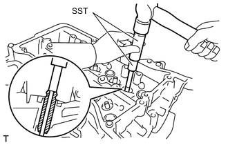
*a Protrusion Height Using SST, tap in new exhaust valve guide bushes to the specified protrusion height.
- SST
- 09201-10000 ( 09201-01050 )
- 09950-70010 ( 09951-07100 )
Standard Protrusion Height 9.10 to 9.90 mm (0.358 to 0.390 in.) -
Using a sharp 5.5 mm reamer, ream the exhaust valve guide bushes to obtain the specified oil clearance.
Standard Oil Clearance 0.025 to 0.065 mm (0.00098 to 0.00256 in.)
-
-
REPLACE RING PIN
Note
It is not necessary to remove the ring pins unless they are being replaced.
-
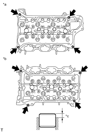
*a for Bank 1 *b for Bank 2 *c Protrusion Height Using a plastic hammer, tap in new ring pins to the specified protrusion height.
Standard Protrusion Height 2.5 to 3.8 mm (0.0984 to 0.150 in.)
-
-
REPLACE STRAIGHT PIN
Note
It is not necessary to remove the straight pins unless they are being replaced.
-
Using a plastic hammer, tap in new straight pins as shown in the illustration.
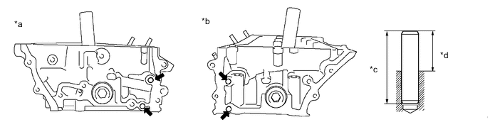
*a for Bank 1 *b for Bank 2 *c 34 mm (1.34 in.) *d Protrusion Height Standard Protrusion Height 18.5 mm (0.728 in.)
-