ENGINE UNIT INSTALLATION

PROCEDURE
-
INSTALL V-BANK COVER BRACKET SUB-ASSEMBLY
-
Install the V-bank cover bracket sub-assembly to the cylinder head cover sub-assembly RH with the bolt.
- Torque:
- 10 N*m { 102 kgf*cm, 7 ft.*lbf }
-
-
INSTALL WIRE HARNESS CLAMP BRACKET
-
Install the wire harness clamp bracket to the camshaft housing sub-assembly RH with the bolt.
- Torque:
- 13 N*m { 133 kgf*cm, 10 ft.*lbf }
-
-
INSTALL ENGINE WIRE
-
Install the engine wire to the engine assembly.
-
-
INSTALL NO. 3 WATER BY-PASS PIPE
-
Connect the No. 9 water by-pass hose to the rear water by-pass joint and slide the clip to secure it.
-
Connect the No. 8 water by-pass hose to the water outlet pipe sub-assembly and slide the clip to secure it.
-
Install the No. 3 water by-pass pipe to the camshaft housing sub-assembly RH with the bolt.
- Torque:
- 10 N*m { 102 kgf*cm, 7 ft.*lbf }
-
-
INSTALL NO. 2 SURGE TANK STAY
-
Install the No. 2 surge tank stay to the camshaft housing sub-assembly LH with the bolt.
- Torque:
- 21 N*m { 214 kgf*cm, 15 ft.*lbf }
-
Connect the 2 clamps to the No. 2 surge tank stay.
-
-
INSTALL NO. 2 FUEL TUBE SUB-ASSEMBLY
-
Install the No. 2 fuel tube sub-assembly with the 2 bolts.
- Torque:
- 10 N*m { 102 kgf*cm, 7 ft.*lbf }
-
Connect the No. 2 fuel tube sub-assembly to the fuel delivery pipe sub-assembly and slide the clip to secure it.
-
-
INSTALL NO. 3 FUEL PIPE SUB-ASSEMBLY
-
INSTALL NO. 2 FUEL PIPE SUB-ASSEMBLY
-
INSTALL INJECTOR DRIVER
-
INSTALL WATER PUMP PULLEY
-
INSTALL V-RIBBED BELT TENSIONER ASSEMBLY
-
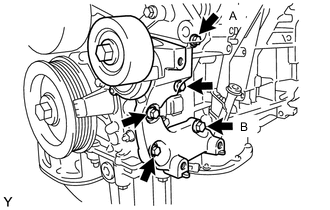
Temporarily install the V-ribbed belt tensioner assembly with the bolt (A) and (B).
-
Tighten the 5 bolts to install the V-ribbed belt tensioner assembly.
- Torque:
- 43 N*m { 438 kgf*cm, 32 ft.*lbf }
-
-
INSTALL FRONT NO. 1 ENGINE MOUNTING BRACKET LH
-
Install the front No. 1 engine mounting bracket LH to the cylinder block sub-assembly with the 4 bolts.
- Torque:
- 43 N*m { 438 kgf*cm, 32 ft.*lbf }
-
Connect the 2 clamps.
-
-
INSTALL FRONT NO. 1 ENGINE MOUNTING BRACKET RH
-
Install the front No. 1 engine mounting bracket RH to the cylinder block sub-assembly with the 4 bolts.
- Torque:
- 43 N*m { 438 kgf*cm, 32 ft.*lbf }
-
-
INSTALL COMPRESSOR AND MAGNETIC CLUTCH
-
INSTALL GENERATOR ASSEMBLY
-
INSTALL NO. 2 IDLER PULLEY SUB-ASSEMBLY
-
INSTALL NO. 1 ENGINE COVER
-
INSTALL NO. 2 ENGINE COVER
-
Install the No. 2 engine cover sub-assembly with the 3 clips.
-
Connect the clamp to the No. 2 engine cover sub-assembly.
-
-
INSTALL V-RIBBED BELT
-
INSTALL IGNITION COIL ASSEMBLY