CYLINDER BLOCK DISASSEMBLY

PROCEDURE
-
INSPECT CONNECTING ROD THRUST CLEARANCE
-
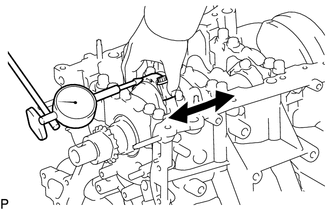
Using a dial indicator, measure the thrust clearance while moving the connecting rod back and forth.
Standard Thrust Clearance 0.15 to 0.40 mm (0.00591 to 0.0157 in.) Maximum Thrust Clearance 0.50 mm (0.0197 in.) Tech Tips
If the thrust clearance is more than the maximum, replace the connecting rod sub-assembly. If necessary, replace the crankshaft.
-
-
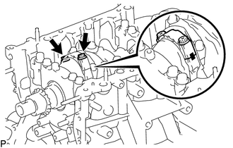
INSPECT CONNECTING ROD OIL CLEARANCE
-
Check that the matchmarks on the connecting rod sub-assembly and connecting rod cap are aligned.
Tech Tips
The matchmarks on the connecting rod sub-assembly and connecting rod cap are guides for correct reassembly.
-
Remove the 2 connecting rod cap bolts.
-
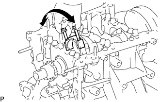
Using the 2 removed connecting rod bolts, remove the connecting rod cap and lower connecting rod bearing by wiggling the connecting rod cap right and left.
Tech Tips
Keep the lower connecting rod bearing installed to the connecting rod cap.
-
Clean the crank pin and connecting rod bearing.
-
Check the crank pin and connecting rod bearing for pitting or scratches.
-
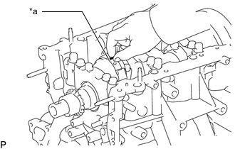
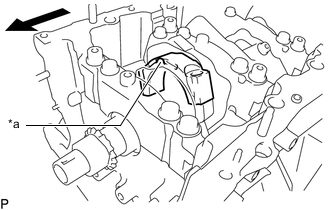
*a Plastigage Lay a strip of Plastigage on the crank pin.
-
*a Plastigage 
Engine Front Ensure that the front mark of the connecting rod cap is facing forward.
-
Install the connecting rod cap with the 2 connecting rod bolts.
Note
Do not turn the crankshaft.
-
Remove the 2 connecting rod bolts and connecting rod cap.
-
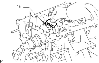
*a Plastigage 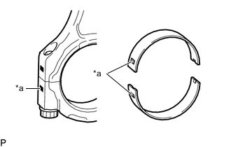
*a Number Mark Measure the Plastigage at its widest point.
Standard Oil Clearance 0.032 to 0.052 mm (0.00126 to 0.00205 in.) Maximum Oil Clearance 0.070 mm (0.00276 in.) Tech Tips
-
If the oil clearance is more than the maximum, replace the connecting rod bearings. If necessary, inspect the crankshaft.
-
If replacing a connecting rod bearing, select a new one with the same number as marked on the connecting rod cap. There are 4 sizes of standard connecting rod bearings, marked "1", "2", "3" or "4" accordingly.
Standard Connecting Rod Diameter Mark Specified Condition 1 56.000 to 56.006 mm (2.20472 to 2.20496 in.) 2 56.007 to 56.012 mm (2.20500 to 2.20519 in.) 3 56.013 to 56.018 mm (2.20523 to 2.20543 in.) 4 56.019 to 56.024 mm (2.20547 to 2.20566 in.) Standard Connecting Rod Bearing Center Wall Thickness Mark Specified Condition 1 1.481 to 1.484 mm (0.0583 to 0.0584 in.) 2 1.484 to 1.487 mm (0.0584 to 0.0585 in.) 3 1.487 to 1.490 mm (0.0585 to 0.0587 in.) 4 1.490 to 1.493 mm (0.0587 to 0.0588 in.) Standard Crankshaft Pin Diameter 52.992 to 53.000 mm (2.08630 to 2.08661 in.) Note
Completely remove the Plastigage after the measurement.
-
-
-
REMOVE PISTON SUB-ASSEMBLY WITH CONNECTING ROD
-
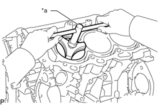
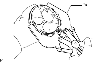
*a Ridge Reamer Using a ridge reamer, remove all of the carbon from the top of the cylinder.
-
Push the piston, connecting rod sub-assembly and upper connecting rod bearing through the top of the cylinder block sub-assembly.
Tech Tips
-
Keep the connecting rod bearing, connecting rod sub-assembly and connecting rod cap together.
-
Arrange the removed parts in such a way that they can be reinstalled to their original locations.
-
-
-
REMOVE CONNECTING ROD BEARING
-
Remove the connecting rod bearings from the connecting rod and connecting rod cap.
Tech Tips
Arrange the removed parts in such a way that they can be reinstalled to their original locations.
-
-
REMOVE CRANKSHAFT
-
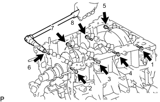
Uniformly loosen and remove the 8 crankshaft bearing cap set bolts and 8 seal washers in several steps in the order shown in the illustration.
-
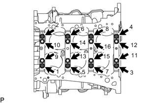
Uniformly loosen the 16 crankshaft bearing cap set bolts in several steps in the order shown in the illustration.
-
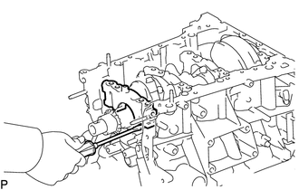
Using a screwdriver with its tip wrapped with protective tape, pry out the crankshaft bearing caps. Remove the 4 crankshaft bearing caps and 4 lower crankshaft bearings as a set.
Note
-
Push up the crankshaft bearing cap slowly and evenly, alternating between the right and left side so that the crankshaft bearing cap can be removed.
-
Be careful not to damage the contact surfaces of the cylinder block sub-assembly and the crankshaft bearing cap.
-
-
Remove the crankshaft.
-
-
REMOVE CRANKSHAFT BEARING
-
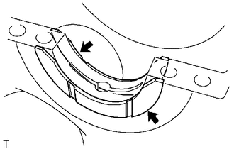
Remove the 4 upper crankshaft bearings and 4 lower crankshaft bearings.
Tech Tips
Arrange the removed parts in such a way that they can be reinstalled to their original locations.
-
-
REMOVE CRANKSHAFT THRUST WASHER SET
-
Remove the crankshaft thrust washer set from the cylinder block sub-assembly.
-
-
REMOVE PISTON RING SET
-
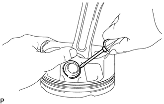
*a Piston Ring Expander Using a piston ring expander, remove the No. 1 compression ring and No. 2 compression ring.
-
Remove the oil ring expander and 2 side rails by hand.
Tech Tips
Arrange the removed parts in such a way that they can be reinstalled to their original locations.
-
-
REMOVE PISTON SUB-ASSEMBLY WITH PIN
-
Remove the connecting rod from the piston.
-
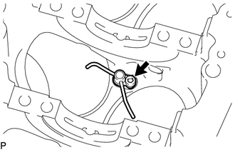
Using a screwdriver, pry out the piston pin hole snap ring (front side).
Note
-
Do not remove the piston pin hole snap ring (rear side) unless it has to be replaced.
-
Be careful not to damage the piston when removing the piston pin hole snap ring (rear side).
-
-
Gradually heat the piston to approximately 80°C (176°F).
CAUTION:
Be sure to wear protective gloves.
-
Using a brass bar and a hammer, lightly tap out the piston pin and remove the connecting rod.
Tech Tips
-
The piston and piston pin are a matched set.
-
Arrange the removed parts in such a way that they can be reinstalled to their original locations.
-
-
-
Using a gasket scraper, remove any carbon from the piston top.
Note
Be careful not to scratch the piston.
-
Using a groove cleaning tool or a broken ring, clean the piston ring grooves.
-
Using solvent and a brush, thoroughly clean the piston.
Note
Do not use a wire brush.
-
-
REMOVE NO. 1 OIL NOZZLE SUB-ASSEMBLY
-
Using a 5 mm hexagon socket wrench, remove the 3 bolts and 3 No. 1 oil nozzle sub-assemblies.
-
Check the 3 No. 1 oil nozzle sub-assemblies for damage or clogging.
Tech Tips
If there is damage or clogs, replace the No. 1 oil nozzle sub-assembly.
-
-
REMOVE CONNECTING ROD SMALL END BUSH
-
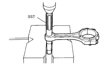
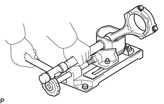
Using SST and a press, press out the connecting rod small end bush.
- SST
- 09222-30010
-