ENGINE UNIT INSTALLATION

PROCEDURE
-
INSTALL THERMOSTAT (for Cylinder Block)
-
INSTALL WATER INLET HOUSING
-
INSTALL OIL PRESSURE SWITCHING VALVE ASSEMBLY
-
INSTALL NO. 4 WATER BY-PASS PIPE
-
Install a new gasket to the water inlet housing.
-
Install the No. 4 water by-pass pipe to the cylinder block sub-assembly and water inlet housing with the bolt and 2 nuts.
- Torque:
- 10 N*m { 102 kgf*cm, 7 ft.*lbf }
-
Connect the No. 4 water by-pass pipe to the oil cooler assembly and slide the clip to secure it.
-
-
INSTALL WATER BY-PASS PIPE ASSEMBLY
-
INSTALL VACUUM PUMP ASSEMBLY
-
INSTALL FUEL INJECTOR SEAL (for Direct Injection)
-
INSTALL DIRECT FUEL INJECTOR ASSEMBLY
-
INSTALL FUEL DELIVERY PIPE SUB-ASSEMBLY (for Direct Injection)
-
INSTALL PORT FUEL INJECTOR ASSEMBLY
-
INSTALL FUEL DELIVERY PIPE (for Port Injection)
-
TEMPORARILY INSTALL FUEL PUMP ASSEMBLY (for High Pressure)
-
TEMPORARILY INSTALL NO. 1 FUEL PIPE SUB-ASSEMBLY (for High Pressure)
-
INSTALL FUEL PUMP ASSEMBLY (for High Pressure)
-
INSTALL NO. 1 FUEL PIPE SUB-ASSEMBLY (for High Pressure)
-
INSTALL AIR CLEANER BRACKET
-
Install the air cleaner bracket to the timing chain cover assembly with the bolt.
- Torque:
- 10 N*m { 102 kgf*cm, 7 ft.*lbf }
-
-
INSTALL NO. 1 TURBO WATER PIPE
-
INSTALL V-RIBBED BELT TENSIONER ASSEMBLY
-
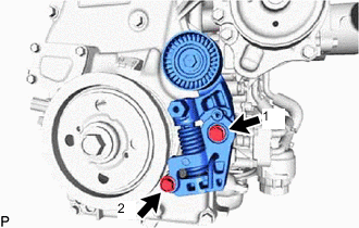
Install the V-ribbed belt tensioner assembly with the 2 bolts in the order shown in the illustration.
- Torque:
- 21 N*m { 214 kgf*cm, 15 ft.*lbf }
-
-
INSTALL IDLER PULLEY SUB-ASSEMBLY
-
Install the idler pulley sub-assembly to the timing chain cover assembly with the bolt.
- Torque:
- 43 N*m { 438 kgf*cm, 32 ft.*lbf }
-
-
INSTALL OIL FILLER CAP GASKET
-
Install the oil filler cap gasket to the oil filler cap sub-assembly.
-
-
INSTALL OIL FILLER CAP SUB-ASSEMBLY
-
Install the oil filler cap sub-assembly to the cylinder head cover sub-assembly.
-
-
INSTALL HOSE BRACKET (for RHD)
-
Install the hose bracket to the cylinder head cover sub-assembly with the bolt.
- Torque:
- 21 N*m { 214 kgf*cm, 15 ft.*lbf }
-
-
INSTALL WIRE HARNESS CLAMP BRACKET
-
Install the wire harness clamp bracket to the timing chain cover assembly with the bolt.
- Torque:
- 10 N*m { 102 kgf*cm, 7 ft.*lbf }
-
Connect the oil pressure sender gauge assembly connector.
-
Install the wire harness clamp bracket to the cylinder head cover sub-assembly with the bolt.
- Torque:
- 10 N*m { 102 kgf*cm, 7 ft.*lbf }
-
Install the 2 wire harness clamp brackets to the stiffening crankcase assembly with the 2 bolts.
- Torque:
- 10 N*m { 102 kgf*cm, 7 ft.*lbf }
-
Install the wire harness clamp bracket to the cylinder head sub-assembly with the bolt.
- Torque:
- 10 N*m { 102 kgf*cm, 7 ft.*lbf }
-
-
INSTALL SENSOR WIRE
-
Install the sensor wire to the fuel delivery pipe sub-assembly with the 2 bolts.
- Torque:
- 8.0 N*m { 82 kgf*cm, 71 in.*lbf }
-
Connect the 4 direct fuel injector assembly connectors.
-
Connect the fuel pressure sensor connector.
-
-
INSTALL NO. 3 EXHAUST MANIFOLD HEAT INSULATOR
-
INSTALL TURBOCHARGER SUB-ASSEMBLY
-
CONNECT INLET TURBO OIL PIPE SUB-ASSEMBLY
-
INSTALL HEAT INSULATOR BRACKET
-
INSTALL COMPRESSOR OUTLET ELBOW
-
Install a new gasket to the turbocharger sub-assembly.
-
Install the compressor outlet elbow to the turbocharger sub-assembly with the 2 nuts.
- Torque:
- 24 N*m { 245 kgf*cm, 18 ft.*lbf }
-
-
INSTALL NO. 5 EXHAUST MANIFOLD HEAT INSULATOR
-
INSTALL NO. 4 VENTILATION HOSE
-
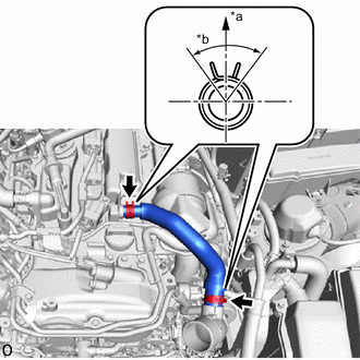
*a Upper Side *b 90° Install the No. 4 ventilation hose with the 2 clips as shown in the illustration.
Tech Tips
Install the clips so that they are positioned as shown in the illustration.
-
-
INSTALL VENTILATION HOSE
-
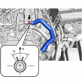
*a Upper Side *b 90° Connect the ventilation hose with the clip as shown in the illustration.
Tech Tips
Install the clip so that it is positioned as shown in the illustration.
-
Attach the clamp.
-
-
INSTALL IGNITION COIL ASSEMBLY
-
INSTALL ENGINE OIL LEVEL DIPSTICK GUIDE
-
Install a new O-ring to the engine oil level dipstick guide.
-
Apply a light coat of engine oil to the O-ring.
-
Install the engine oil level dipstick guide with the bolt.
- Torque:
- 10 N*m { 102 kgf*cm, 7 ft.*lbf }
-
Install the engine oil level dipstick.
-
-
INSTALL FRONT NO. 1 ENGINE MOUNTING BRACKET RH
-
Install the front No. 1 engine mounting bracket RH to the cylinder block sub-assembly with the 4 bolts.
- Torque:
- 43 N*m { 438 kgf*cm, 32 ft.*lbf }
-
-
INSTALL FRONT NO. 1 ENGINE MOUNTING BRACKET LH
-
Install the front No. 1 engine mounting bracket LH to the cylinder block sub-assembly with the 4 bolts.
- Torque:
- 43 N*m { 438 kgf*cm, 32 ft.*lbf }
-
-
INSTALL FRONT ENGINE MOUNTING HEAT INSULATOR LH (w/ Front Engine Mounting Heat Insulator LH)
-
Install the front engine mounting heat insulator LH to the front No. 1 engine mounting bracket LH with the 2 bolts.
- Torque:
- 8.0 N*m { 82 kgf*cm, 71 in.*lbf }
-
-
INSTALL INTAKE MANIFOLD WITH INTERCOOLER ASSEMBLY AND THROTTLE WITH MOTOR BODY ASSEMBLY
-
Install 2 new No. 1 intake manifold to head gaskets to the intake manifold with intercooler assembly and throttle with motor body assembly.
-
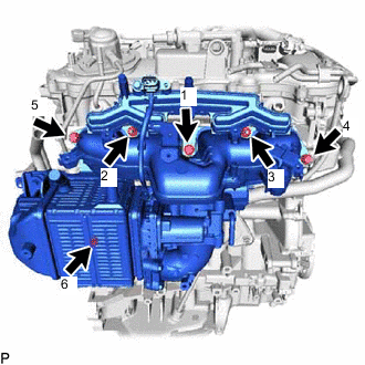
Temporarily install the intake manifold with intercooler assembly and throttle with motor body assembly with the 4 bolts and 2 nuts.
-
Tighten the 4 bolts and 2 nuts in the order shown in the illustration.
- Torque:
- 21 N*m { 214 kgf*cm, 15 ft.*lbf }
-
Install the wire harness clamp bracket to the intake manifold with intercooler assembly and throttle with motor body assembly with the bolt.
- Torque:
- 10 N*m { 102 kgf*cm, 7 ft.*lbf }
-
-
CONNECT NO. 3 WATER BY-PASS HOSE
-
Connect the No. 3 water by-pass hose to the water outlet sub-assembly and slide the clip to secure it.
-
Engage the clamp to the engine oil level dipstick guide.
-
-
INSTALL NO. 2 VENTILATION HOSE
-
CONNECT VACUUM TRANSMITTING HOSE ASSEMBLY
-
CONNECT NO. 2 VACUUM TRANSMITTING HOSE ASSEMBLY
-
INSTALL PURGE VALVE (PURGE VSV)
w/ Canister Pump Module: Click here
w/o Canister Pump Module: Click here
-
INSTALL WATER BY-PASS PIPE ASSEMBLY
-
Install the water by-pass pipe assembly to the intercooler assembly and No. 2 air tube with the 2 bolts.
- Torque:
- 10 N*m { 102 kgf*cm, 7 ft.*lbf }
-
Connect the No. 9 water by-pass hose to the intercooler assembly and slide the clip to secure it.
-
Connect the No. 2 turbo water hose to the No. 1 turbo water pipe sub-assembly and slide the clip to secure it.
-
-
INSTALL NO. 2 WATER BY-PASS PIPE
-
INSTALL NO. 1 COMPRESSOR MOUNTING BRACKET
-
INSTALL COMPRESSOR AND MAGNETIC CLUTCH
-
INSTALL GENERATOR ASSEMBLY