CYLINDER HEAD GASKET INSTALLATION
CAUTION / NOTICE / HINT
Tech Tips
Perform "Inspection After Repair" after replacing the cylinder head sub-assembly.
-
w/ Canister Pump Module:
-
w/o Canister Pump Module:
PROCEDURE
-
INSTALL CYLINDER HEAD GASKET
-
Clean the cylinder block sub-assembly and cylinder head sub-assembly with solvent.
-
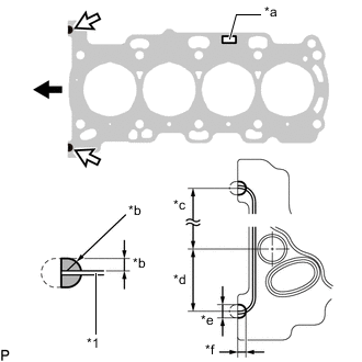
*1 Cylinder Head Gasket *a Lot No. *b 3.0 to 5.0 mm (0.118 to 0.197 in.) *c 152.5 mm (6.00 in.) *d 38 mm (1.50 in.) *e 7.0 to 9.0 mm (0.276 to 0.354 in.) *f 5.0 to 7.0 mm (0.197 to 0.276 in.) 
Front of Engine 
Seal Packing Application Area Apply seal packing to a new cylinder head gasket as shown in the illustration.
Note
-
Remove any oil from the contact surface.
-
Install the cylinder head gasket within 3 minutes and tighten the bolts within 10 minutes applying seal packing.
-
-
Place the cylinder head gasket on the cylinder block sub-assembly as shown in the illustration.
Note
-
Remove any oil from the contact surface.
-
Make sure that the cylinder head gasket is installed in the correct orientation.
-
Do not damage the cylinder head gasket.
-
-
-
INSTALL CYLINDER HEAD SUB-ASSEMBLY
Tech Tips
Perform "Inspection After Repair" after replacing the cylinder head sub-assembly.
-
w/ Canister Pump Module:
-
w/o Canister Pump Module:
-
Clean the cylinder head sub-assembly with solvent.
-
Place the cylinder head sub-assembly on the cylinder block sub-assembly.
Note
-
Check and clean the cylinder head set bolts and bolt holes.
-
Make sure there is no oil on the contact surface of the cylinder head sub-assembly.
-
Gently place the cylinder head sub-assembly in order not to damage the cylinder head gasket.
-
-
Apply a light coat of engine oil to the threads and under the heads of the cylinder head set bolts.
-
Install the 10 plate washers to the 10 cylinder head set bolts.
Note
-
Install the cylinder head set bolts to the same place they were removed from.
-
Be careful not to drop the plate washers into the cylinder head sub-assembly.
Tech Tips
The cylinder head set bolts are tightened in 3 progressive steps.
-
-
Step 1:
-
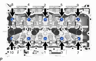
Using a 10 mm bi-hexagon wrench, install and uniformly tighten the 10 cylinder head set bolts in several steps in the order shown in the illustration.
- Torque:
- 85 N*m { 867 kgf*cm, 63 ft.*lbf }
-
-
Step 2:
-
Mark the front of each cylinder head set bolt head with paint.
-
Tighten the cylinder head set bolts an additional 90°.
-
-
Step 3:
-
Tighten the cylinder head set bolts an additional 90°.
-
Check that the paint marks are now at a 180° angle to the front of the engine.
Note
After installing the cylinder head sub-assembly, wipe off any excess seal packing within 5 minutes.
-
-
-
INSTALL VALVE STEM CAP
-
INSTALL VALVE LASH ADJUSTER ASSEMBLY
-
INSTALL NO. 1 VALVE ROCKER ARM SUB-ASSEMBLY
-
INSTALL NO. 3 WATER BY-PASS PIPE
-
INSTALL CAMSHAFT HOUSING SUB-ASSEMBLY
-
INSTALL CAMSHAFT TIMING GEAR ASSEMBLY
-
INSTALL CAMSHAFT TIMING EXHAUST GEAR ASSEMBLY
-
ADD ENGINE OIL
-
INSTALL NO. 1 CHAIN VIBRATION DAMPER
-
INSTALL CHAIN SUB-ASSEMBLY
-
INSTALL CHAIN TENSIONER SLIPPER
-
INSTALL TIMING CHAIN GUIDE
-
INSTALL NO. 1 CHAIN TENSIONER ASSEMBLY
-
SET NO. 1 CYLINDER TO TDC/COMPRESSION
-
INSTALL TIMING CHAIN COVER ASSEMBLY
-
INSTALL TIMING CHAIN COVER OIL SEAL
-
INSTALL CRANKSHAFT POSITION SENSOR
-
INSTALL CRANKSHAFT PULLEY ASSEMBLY
-
INSTALL V-RIBBED BELT TENSIONER ASSEMBLY
-
INSTALL IDLER PULLEY SUB-ASSEMBLY
-
INSTALL CAMSHAFT TIMING OIL CONTROL SOLENOID ASSEMBLY
-
INSTALL WATER OUTLET SUB-ASSEMBLY
-
INSTALL AIR CLEANER BRACKET
-
INSTALL ENGINE OIL LEVEL DIPSTICK GUIDE
-
INSTALL NO. 6 WATER BY-PASS HOSE
-
INSTALL CYLINDER HEAD COVER GASKET
-
INSTALL CYLINDER HEAD COVER SUB-ASSEMBLY
-
INSTALL NO. 3 VENTILATION HOSE
-
INSTALL NO. 1 TURBO WATER PIPE
-
INSTALL IGNITION COIL ASSEMBLY
-
INSTALL VACUUM PUMP ASSEMBLY
-
INSTALL FUEL PUMP ASSEMBLY (for High Pressure)
-
INSTALL DIRECT FUEL INJECTOR ASSEMBLY
-
INSTALL TURBOCHARGER SUB-ASSEMBLY