CAMSHAFT INSTALLATION

CAUTION / NOTICE / HINT
Tech Tips
Perform "Inspection After Repair" after replacing the camshaft, No. 2 camshaft, camshaft timing gear assembly or camshaft timing exhaust gear assembly.
-
w/ Canister Pump Module:
-
w/o Canister Pump Module:
PROCEDURE
-
INSTALL NO. 2 CAMSHAFT BEARING
-
INSTALL NO. 1 CAMSHAFT BEARING
-
INSTALL OIL CONTROL VALVE FILTER
-
INSTALL CAMSHAFT TIMING EXHAUST GEAR ASSEMBLY
Tech Tips
Perform "Inspection After Repair" after replacing the camshaft timing exhaust gear assembly.
-
w/ Canister Pump Module:
-
w/o Canister Pump Module:
-
Secure the No. 2 camshaft in a vise between aluminum plates.
-
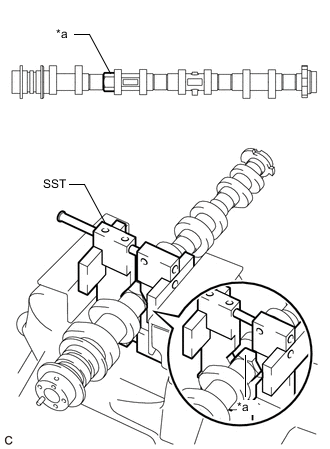
*a Hexagonal Portion Using SST, grip the hexagonal portion, and then secure the SST and No. 2 camshaft in a vise as shown in the illustration.
- SST
- 09212-31010
Note
-
Do not damage the No. 2 camshaft.
-
Never grip areas other than the hexagonal portion, as this may cause damage.
-
-
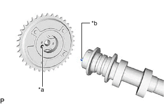
*a Knock Pin Hole *b Knock Pin Align and fit the knock pin of the No. 2 camshaft to the knock pin hole of the camshaft timing exhaust gear assembly.
-
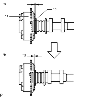
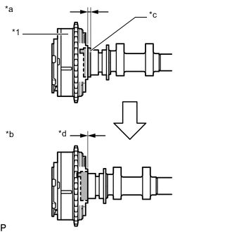
*1 Camshaft Timing Exhaust Gear Assembly *a Incorrect *b Correct *c No. 2 Camshaft Flange *d No gap Check that there is no gap between the camshaft timing exhaust gear assembly and No. 2 camshaft flange.
-
Temporarily install the camshaft timing exhaust gear assembly to the No. 2 camshaft with the bolt.
-
Tighten the bolt.
- Torque:
- 85 N*m { 867 kgf*cm, 63 ft.*lbf }
Note
-
Do not damage the No. 2 camshaft or camshaft timing exhaust gear assembly.
-
Do not disassemble the camshaft timing exhaust gear assembly.
-
-
SET NO. 1 CYLINDER TO TDC/COMPRESSION
-
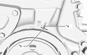
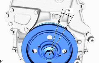
*a Timing Mark "0" *b Timing Mark (Groove) Turn the crankshaft until the timing mark (groove) of the crankshaft pulley assembly and the timing mark "0" of the timing chain cover assembly are aligned.
-
-
INSTALL NO. 2 CAMSHAFT
Note
When installing the camshaft housing sub-assembly, it is necessary to correctly position the camshafts as shown in the illustration. Failure to correctly position the camshafts may result in damage due to contact between the pistons and valves. If a camshaft is rotated with a piston at TDC, valve contact will occur.
Tech Tips
Perform "Inspection After Repair" after replacing the No. 2 camshaft.
-
w/ Canister Pump Module:
-
w/o Canister Pump Module:
-
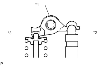
*1 No. 1 Valve Rocker Arm Sub-assembly *2 Valve Lash Adjuster Assembly *3 Valve Stem Cap Check that the No. 1 valve rocker arm sub-assemblies are installed as shown in the illustration.
-
Apply a light coat of engine oil to the No. 2 camshaft journals and camshaft housing sub-assembly.
-
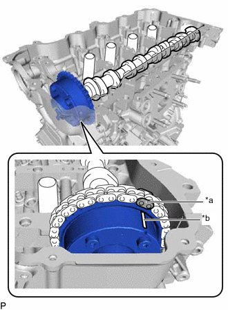
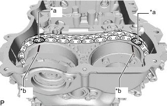
*a Paint Mark *b Timing Mark (Groove) Align the paint mark of the chain sub-assembly and the timing mark (groove) of the camshaft timing exhaust gear assembly. Then install the No. 2 camshaft and camshaft timing exhaust gear assembly.
-
-
INSTALL CAMSHAFT TIMING GEAR ASSEMBLY
Tech Tips
Perform "Inspection After Repair" after replacing the camshaft timing gear assembly.
-
w/ Canister Pump Module:
-
w/o Canister Pump Module:
-
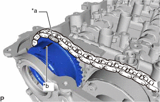
*a Paint Mark *b Timing Mark (Groove) Align the paint mark of the chain sub-assembly and the timing mark (groove) of the camshaft timing gear assembly. Then install the camshaft timing gear assembly.
Note
Do not disassemble the camshaft timing gear assembly.
-
-
INSTALL CAMSHAFT
Note
When installing the camshaft housing sub-assembly, it is necessary to correctly position the camshafts as shown in the illustration. Failure to correctly position the camshafts may result in damage due to contact between the pistons and valves. If a camshaft is rotated with a piston at TDC, valve contact will occur.
Tech Tips
Perform "Inspection After Repair" after replacing the camshaft.
-
w/ Canister Pump Module:
-
w/o Canister Pump Module:
-
*1 No. 1 Valve Rocker Arm Sub-assembly *2 Valve Lash Adjuster Assembly *3 Valve Stem Cap Check that the No. 1 valve rocker arm sub-assemblies are installed as shown in the illustration.
-
Apply a light coat of engine oil to the camshaft journals and camshaft housing sub-assembly.
-
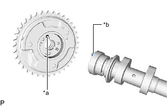
*a Knock Pin Hole *b Knock Pin Align and fit the knock pin of the camshaft to the knock pin hole of the camshaft timing gear assembly.
-
*1 Camshaft Timing Gear Assembly *a Incorrect *b Correct *c Camshaft Flange *d No gap Check that there is no gap between the camshaft timing gear assembly and camshaft flange.
-
-
TEMPORARILY INSTALL CAMSHAFT TIMING GEAR BOLT
Note
There are several different types of camshaft timing gear bolt. Make sure to check the identification mark to determine the tightening torque.
Identification Mark Item Identification Mark Type A A Type B C 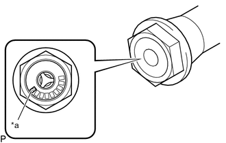
*a Identification Mark
-
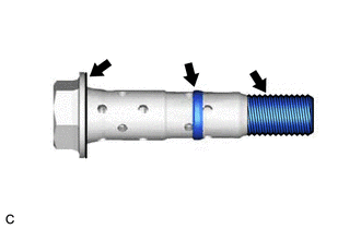
Apply engine oil to the areas of the camshaft timing gear bolt shown in the illustration.
-
Temporarily install the camshaft timing gear bolt to the camshaft.
Tech Tips
Temporarily install the camshaft timing gear bolt until 2 or 3 threads are screwed into the camshaft.
-
-
INSTALL CAMSHAFT BEARING CAP
-
Place the No. 1 camshaft bearing cap, No. 2 camshaft bearing cap, No. 3 camshaft bearing cap and No. 4 camshaft bearing cap to the camshaft housing sub-assembly.
-
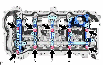
Install the 10 bolts in the order shown in the illustration.
- Torque:
- 27 N*m { 275 kgf*cm, 20 ft.*lbf }
-
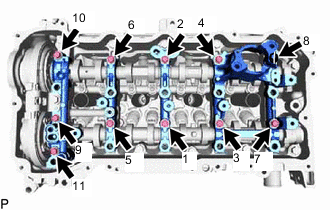
Install the 11 bolts in the order shown in the illustration.
- Torque:
- 16 N*m { 163 kgf*cm, 12 ft.*lbf }
-
-
TIGHTEN CAMSHAFT TIMING GEAR BOLT
Note
There are several different types of camshaft timing gear bolt. Make sure to check the identification mark to determine the tightening torque.
Identification Mark Item Identification Mark Type A A Type B C
*a Identification Mark
-
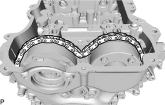
Check that the chain sub-assembly is loose as shown in the illustration.
-
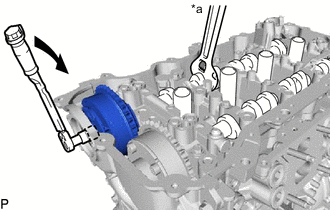
*a Hold 
Turn Using a wrench to hold the hexagonal portion of the camshaft, tighten the camshaft timing gear bolt.
- Torque:
- Type A
- 120 N*m { 1224 kgf*cm, 89 ft.*lbf }
- Type B
- 95 N*m { 969 kgf*cm, 70 ft.*lbf }
Note
Be careful not to damage the camshaft housing sub-assembly or spark plug tube with the wrench.
-
*a Paint Mark *b Timing Mark (Groove) Check that each timing mark (groove) of the camshaft timing gear assembly and camshaft timing exhaust gear assembly is aligned with each paint mark as shown in the illustration.
-
-
ADD ENGINE OIL
-
INSTALL CAMSHAFT TIMING OIL CONTROL SOLENOID ASSEMBLY
-
INSTALL TIMING CHAIN GUIDE
-
INSTALL NO. 1 CHAIN TENSIONER ASSEMBLY
-
*a Approximately 15° Turn the crankshaft approximately 15° clockwise.
-
Temporarily install a new gasket and the No. 1 chain tensioner assembly to the cylinder block sub-assembly with the nut and bolt.
Note
Be careful not to drop the gasket into the timing chain cover assembly.
-
Tighten the nut and bolt.
- Torque:
- 10 N*m { 102 kgf*cm, 7 ft.*lbf }
-
Remove the pin from the stopper plate.
-
-
CHECK NO. 1 CYLINDER TDC/COMPRESSION
-
Turn the crankshaft until the timing mark (groove) of the crankshaft pulley assembly and the timing mark "0" of the timing chain cover assembly are aligned.
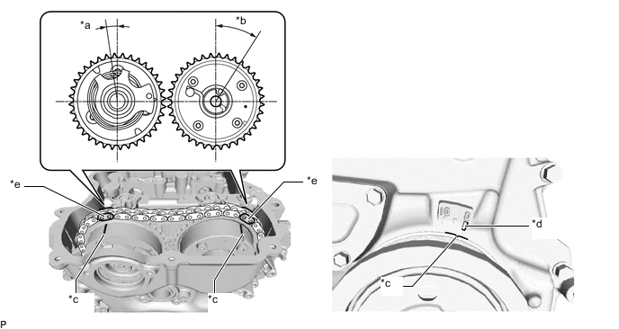
*a Approximately 7° *b Approximately 32° *c Timing Mark (Groove) *d Timing Mark "0" *e Paint Mark - - -
Check that each timing mark (groove) of the camshaft timing gear assembly and camshaft timing exhaust gear assembly is aligned with each paint mark as shown in the illustration.
-
-
INSTALL TIMING CHAIN COVER PLATE
-
INSTALL CYLINDER HEAD COVER GASKET
-
INSTALL CYLINDER HEAD COVER SUB-ASSEMBLY
-
INSTALL VACUUM PUMP ASSEMBLY
-
INSTALL NO. 1 TURBO WATER PIPE
-
Install the No. 1 turbo water pipe to the cylinder head cover sub-assembly with the 3 bolts.
- Torque:
- 10 N*m { 102 kgf*cm, 7 ft.*lbf }
-
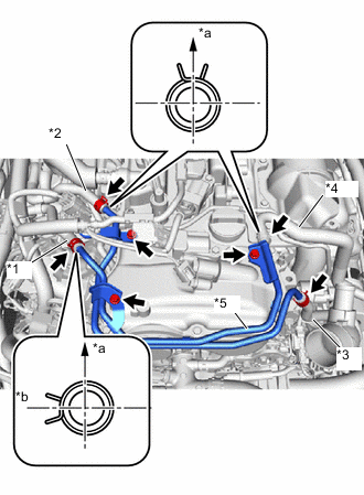
*1 No. 1 Turbo Water By-pass Hose *2 No. 2 Turbo Water By-pass Hose *3 No. 3 Turbo Water By-pass Hose *4 No. 4 Turbo Water By-pass Hose *5 No. 1 Turbo Water Pipe *a Upper Side *b RH Side Connect the No. 1, No. 2, No. 3 and No. 4 turbo water by-pass hoses with the 4 clips as shown in the illustration.
Tech Tips
Install the clips so that they are positioned as shown in the illustration.
-
-
CONNECT ENGINE WIRE
-
Connect the engine wire to the cylinder head cover sub-assembly with the bolt.
- Torque:
- 10 N*m { 102 kgf*cm, 7 ft.*lbf }
-
Engage the clamp and connect the No. 3 ventilation hose to the engine wire.
-
Connect the air fuel ratio sensor connector.
-
Connect the 2 connectors to the 2 camshaft position sensors.
-
-
INSTALL CAMSHAFT TIMING OIL CONTROL VALVE ASSEMBLY
-
INSTALL IGNITION COIL ASSEMBLY
-
CONNECT NO. 2 VENTILATION HOSE
-
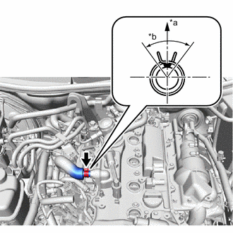
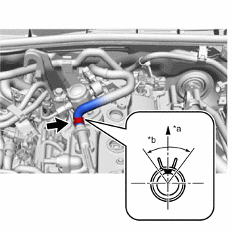
*a Upper Side *b 90° Connect the No. 2 ventilation hose to the cylinder head cover sub-assembly and slide the clip to secure it.
Tech Tips
Install the clip so that it is positioned as shown in the illustration.
-
-
CONNECT NO. 3 VENTILATION HOSE
-
*a Upper Side *b 90° Connect the No. 3 ventilation hose to the cylinder head cover sub-assembly and slide the clip to secure it.
Tech Tips
Install the clip so that it is positioned as shown in the illustration.
-
-
INSTALL NO. 4 VENTILATION HOSE
-
INSTALL VENTILATION HOSE
-
INSTALL FUEL PUMP ASSEMBLY (for High Pressure)
-
INSTALL RADIATOR ASSEMBLY
-
CHECK ENGINE OIL LEVEL