CYLINDER HEAD GASKET REMOVAL

PROCEDURE
-
REMOVE TIMING CHAIN COVER SUB-ASSEMBLY
-
SET NO. 1 CYLINDER TO TDC / COMPRESSION
-
REMOVE NO. 1 CHAIN TENSIONER ASSEMBLY
-
REMOVE CHAIN TENSIONER SLIPPER
-
REMOVE CHAIN SUB-ASSEMBLY
-
REMOVE CAMSHAFT TIMING GEARS AND NO. 2 CHAIN SUB-ASSEMBLY (for Bank 1)
-
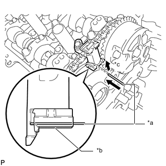
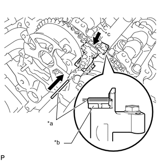
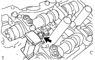
*a Pin *b Plunger *c Push While raising the No. 2 chain tensioner assembly, insert a pin of 1.0 mm (0.0394 in.) diameter into the hole to hold the No. 2 chain tensioner assembly.
-
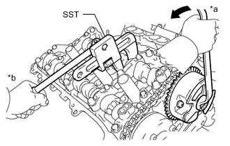
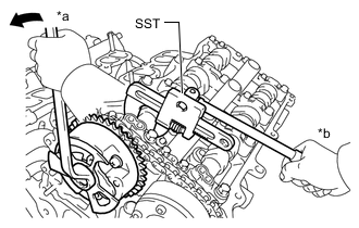
*a Turn *b Hold Using SST to hold the hexagonal portion of each camshaft, loosen the flange bolts of the camshaft timing gear assembly and the camshaft timing exhaust gear assembly RH.
- SST
- 09922-10010
Note
-
Be careful not to damage the cylinder head sub-assembly RH with SST.
-
Do not loosen the other bolts. If any of the bolts is loosened, replace the camshaft timing gear assembly and/or the camshaft timing exhaust gear assembly RH with a new one.
-
Remove the 2 bolts, camshaft timing gear assembly and camshaft timing exhaust gear assembly RH together with the No. 2 chain sub-assembly.
-
Remove the No. 2 chain sub-assembly.
-
-
REMOVE NO. 2 CHAIN TENSIONER ASSEMBLY
-
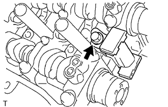
Remove the bolt and No. 2 chain tensioner assembly.
-
-
REMOVE CAMSHAFT BEARING CAP (for Bank 1)
-
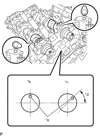
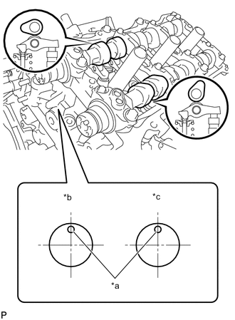
*a Knock Pin *b Exhaust *c Intake *d 45° Check that the camshafts are positioned as shown in the illustration.
-
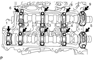
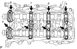
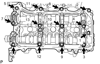
Uniformly loosen and remove the 9 bolts in several steps in the order shown in the illustration.
-
Uniformly loosen and remove the 14 bolts in several steps in the order shown in the illustration.
Note
Uniformly loosen the bolts while keeping the camshafts level.
-
Remove the 6 camshaft bearing caps.
Tech Tips
Arrange the removed parts in such a way that they can be reinstalled to their original locations.
-
-
REMOVE CAMSHAFT
-
Remove the camshaft from the camshaft housing sub-assembly RH.
-
-
REMOVE NO. 2 CAMSHAFT
-
Remove the No. 2 camshaft from the camshaft housing sub-assembly RH.
-
-
REMOVE CAMSHAFT HOUSING SUB-ASSEMBLY RH
-
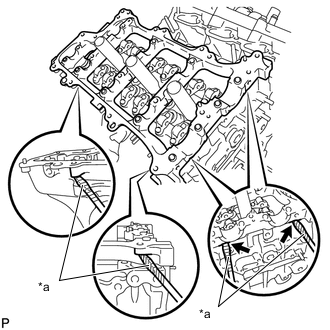
*a Protective Tape Remove the camshaft housing sub-assembly RH by prying between the cylinder head sub-assembly RH and camshaft housing sub-assembly RH with a screwdriver.
Note
Be careful not to damage the contact surfaces of the cylinder head sub-assembly RH and camshaft housing sub-assembly RH.
Tech Tips
Tape the screwdriver tip before use.
-
-
REMOVE CAMSHAFT TIMING GEARS AND NO. 2 CHAIN SUB-ASSEMBLY (for Bank 2)
-
*a Pin *b Plunger *c Push While pushing down the No. 3 chain tensioner assembly, insert a pin of 1.0 mm (0.0394 in.) diameter into the hole to hold the No. 3 chain tensioner assembly.
-
*a Turn *b Hold Using SST to hold the hexagonal portion of each camshaft, loosen the flange bolts of the camshaft timing gear assembly and the camshaft timing exhaust gear assembly LH.
- SST
- 09922-10010
Note
-
Be careful not to damage the cylinder head sub-assembly LH with SST.
-
Do not loosen the other bolts. If any of the bolts is loosened, replace the camshaft timing gear assembly and/or the camshaft timing exhaust gear assembly LH with a new one.
-
Remove the 2 bolts, camshaft timing gear assembly and camshaft timing exhaust gear assembly LH together with the No. 2 chain sub-assembly.
-
Remove the No. 2 chain sub-assembly.
-
-
REMOVE NO. 3 CHAIN TENSIONER ASSEMBLY
-
Remove the bolt and No. 3 chain tensioner assembly.
-
-
REMOVE CAMSHAFT BEARING CAP (for Bank 2)
-
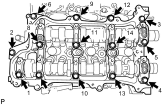
*a Knock Pin *b Intake *c Exhaust Check that the camshafts are positioned as shown in the illustration.
-
Uniformly loosen and remove the 8 bolts in several steps in the order shown in the illustration.
-
Uniformly loosen and remove the 13 bolts in several steps in the order shown in the illustration.
Note
Uniformly loosen the bolts while keeping the camshafts level.
-
Remove the 5 camshaft bearing caps.
Tech Tips
Arrange the removed parts in such a way that they can be reinstalled to their original locations.
-
-
REMOVE NO. 3 CAMSHAFT SUB-ASSEMBLY
-
Remove the No. 3 camshaft sub-assembly from the camshaft housing sub-assembly LH.
-
-
REMOVE NO. 4 CAMSHAFT SUB-ASSEMBLY
-
Remove the No. 4 camshaft sub-assembly from the camshaft housing sub-assembly LH.
-
-
REMOVE CAMSHAFT HOUSING SUB-ASSEMBLY LH
-
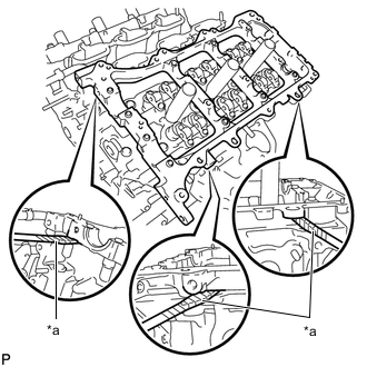
*a Protective Tape Remove the camshaft housing sub-assembly LH by prying between the cylinder head sub-assembly LH and camshaft housing sub-assembly LH with a screwdriver.
Note
Be careful not to damage the contact surfaces of the cylinder head sub-assembly LH and camshaft housing sub-assembly LH.
Tech Tips
Tape the screwdriver tip before use.
-
-
REMOVE NO. 1 CHAIN VIBRATION DAMPER
-
REMOVE NO. 2 CHAIN VIBRATION DAMPER
-
REMOVE NO. 1 VALVE ROCKER ARM SUB-ASSEMBLY
-
Remove the 24 No. 1 valve rocker arm sub-assemblies.
Tech Tips
Arrange the removed parts in such a way that they can be reinstalled to their original locations.
-
-
REMOVE VALVE LASH ADJUSTER ASSEMBLY
-
Remove the 24 valve lash adjuster assemblies.
Tech Tips
Arrange the removed parts in such a way that they can be reinstalled to their original locations.
-
-
REMOVE VALVE STEM CAP
-
Remove the 24 valve stem caps.
Tech Tips
Arrange the removed parts in such a way that they can be reinstalled to their original locations.
-
-
REMOVE REAR WATER BY-PASS JOINT
-
REMOVE FUEL INJECTOR SEAL
-
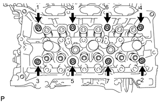
REMOVE CYLINDER HEAD SUB-ASSEMBLY RH
-
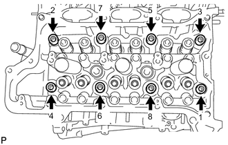
Using a 10 mm bi-hexagon wrench, uniformly loosen the 8 cylinder head set bolts in the order shown in the illustration.
Remove the 8 cylinder head set bolts and plate washers.
Note
-
Be careful not to drop the plate washers into the cylinder head sub-assembly RH.
-
cylinder head sub-assembly RH warpage or cracking could result from removing the cylinder head set bolts in an incorrect order.
Tech Tips
Arrange the removed parts in such a way that they can be reinstalled to their original locations.
-
-
Remove the cylinder head sub-assembly RH.
-
-
REMOVE CYLINDER HEAD GASKET
-
Remove the cylinder head gasket.
Note
-
Clean the bolt holes of the cylinder block sub-assembly and check for damage.
-
If the bolt holes are damaged, repair them with a tap.
-
-
-
REMOVE CYLINDER HEAD SUB-ASSEMBLY LH
-
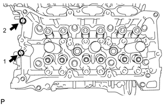
Uniformly loosen and remove the 2 bolts in the order shown in the illustration.
-
Using a 10 mm bi-hexagon wrench, uniformly loosen the 8 cylinder head set bolts in the order shown in the illustration.
Remove the 8 cylinder head set bolts and plate washers.
Note
-
Be careful not to drop the plate washers into the cylinder head sub-assembly LH.
-
Warpage or cracking of the cylinder head sub-assembly LH could result from removing the cylinder head set bolts in an incorrect order.
Tech Tips
Arrange the removed parts in such a way that they can be reinstalled to their original locations.
-
-
Remove the cylinder head sub-assembly LH.
-
-
REMOVE NO. 2 CYLINDER HEAD GASKET
-
Remove the No. 2 cylinder head gasket.
Note
-
Clean the bolt holes of the cylinder block sub-assembly and check for damage.
-
If the bolt holes are damaged, repair them with a tap.
-
-
-
INSPECT CYLINDER HEAD SUB-ASSEMBLY FOR FLATNESS
-
INSPECT CYLINDER HEAD SUB-ASSEMBLY FOR CRACKS
-
INSPECT CYLINDER HEAD SET BOLT
-
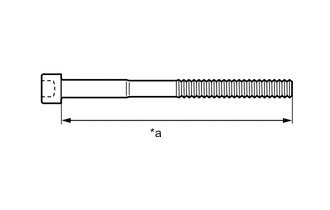
*a Measurement Length Using a vernier caliper, measure the length of the cylinder head set bolt from the seat to the end.
Standard Length 141.3 to 142.7 mm (5.56 to 5.62 in.) Maximum Length 143.7 mm (5.66 in.) Tech Tips
If the length is more than the maximum, replace the cylinder head set bolt.
-
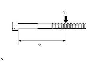
*a Approximately 100 mm (3.94 in.) *b Measurement Point Using a vernier caliper, measure the diameter of the threads at the measurement point.
Standard Diameter 10.80 to 11.00 mm (0.425 to 0.433 in.) Minimum Diameter 10.70 mm (0.421 in.) Note
-
If the diameter is less than the minimum, replace the cylinder head set bolt. Failure to do so may lead to engine damage.
-
If there is any thread deformation, replace the cylinder head set bolt with a new one.
-
-